Brushless motor

Inactive Publication Date: 2013-04-25
MITSUBA CORP
View PDF12 Cites 48 Cited by
  • Summary
  • Abstract
  • Description
  • Claims
  • Application Information

AI Technical Summary

Benefits of technology

[0016]The brushless motor according to the present invention comprises: a cylindrical motor case that is formed from steel plate by press molding is secured, and in which the stator core is secured; a supporting member that is provided on one side in an axial direction of the motor case, and by which a tip side of a rotary shaft secured to the rotor is rotatably supported; and a housing member that is provided on the other side in the axial direction of the motor case, in which a control device for controlling the rotation of the rotor is accommodated, and that is made of aluminum, wherein the control device comprises a power-related circuit board disposed on a bottom side of the housing member and a control-related circuit board disposed on an opening side of the housing member, power-related electronic components being disposed on the power-related circuit board in contact with the housing member. Thus, the brushless motor can be formed by the cylindrical motor case formed from steel plate by press molding and the bottomed housing member made of aluminum. Therefore, it is possible to sufficiently ensure the heat radiation performance of the control device, and in comparison with a conventional motor case made of aluminum, by eliminating the dimension adjusting operation (secondary operation) or the like, it is possible to simplify the producing process and consequently to reduce the production cost. Furthermore, in comparison with the conventional motor case made of aluminum and inevitably increased in thickness, it is possible to provide a motor case reduced in thickness by using a steel plate, and consequently the brushless motor can be improved in size and weight.
[0017]Since, in the brushless motor according to the present invention, a bottom wall is integrally formed on the other side in the axial direction of the motor case and formed with a through hole in which a base end side of the rotary shaft is inserted, and a magnetic rotary sensor for detecting the rotation of the rotary shaft is arranged on the base end side of the rotary shaft extending from the through hole. It is possible to shield a magnetic field generated upon driving the brushless motor from leaking externally by the bottom walls made of steel plate (magnetic material). Thus, it is possible to positively prevent erroneous detection of

Problems solved by technology

Therefore, this leads to the complicated producing process of this motor, a problem about high production cost, the motor case a

Method used


Image

  • Brushless motor
  • Brushless motor
  • Brushless motor

Examples


Embodiment Construction

[0031]Hereinafter, one embodiment of the present invention will be described in detail with reference to the drawings.

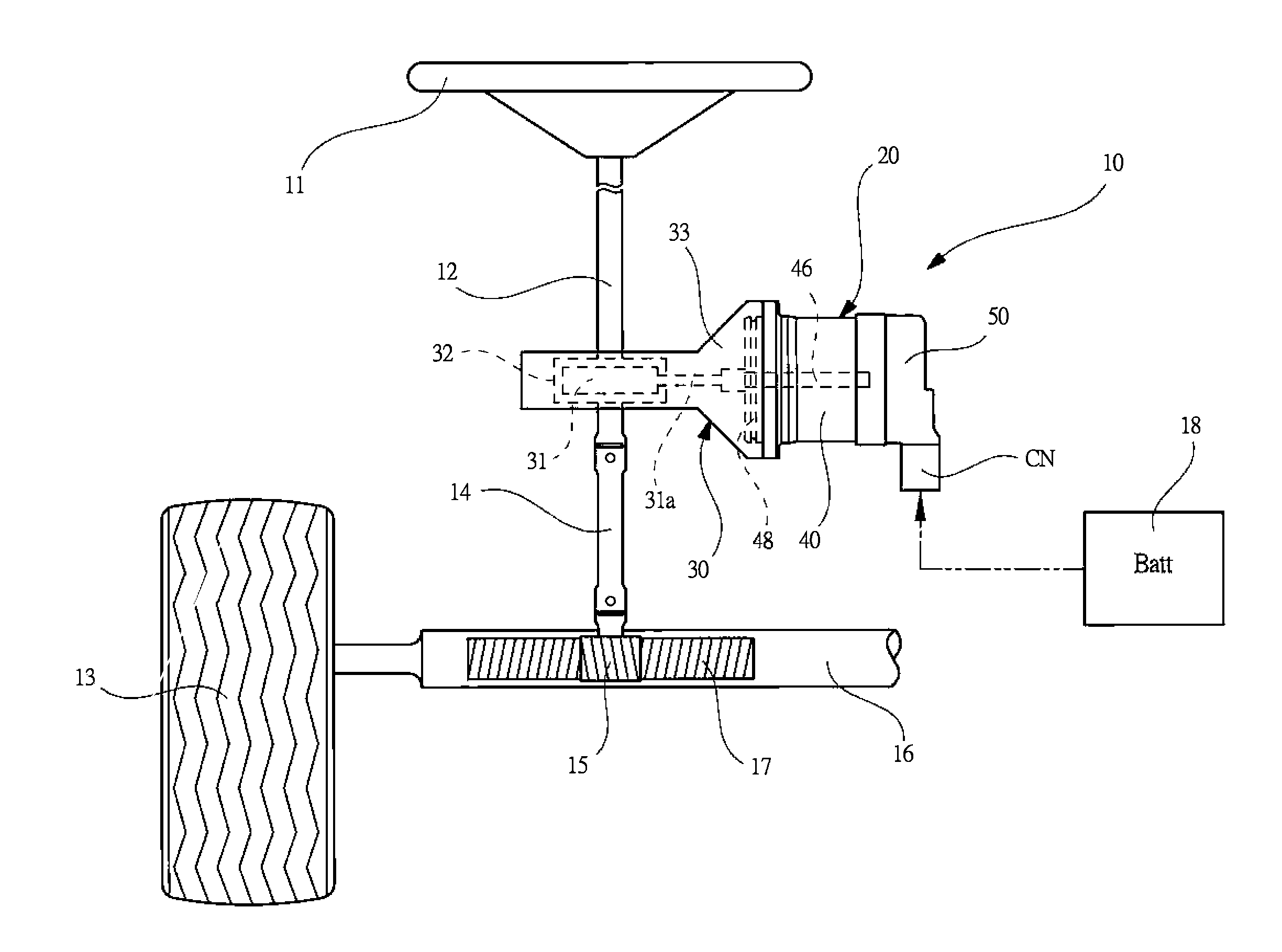
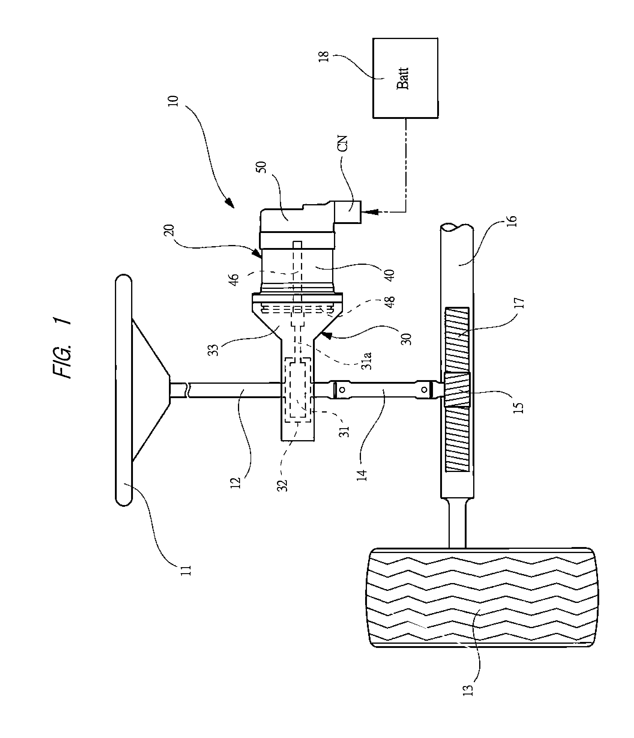
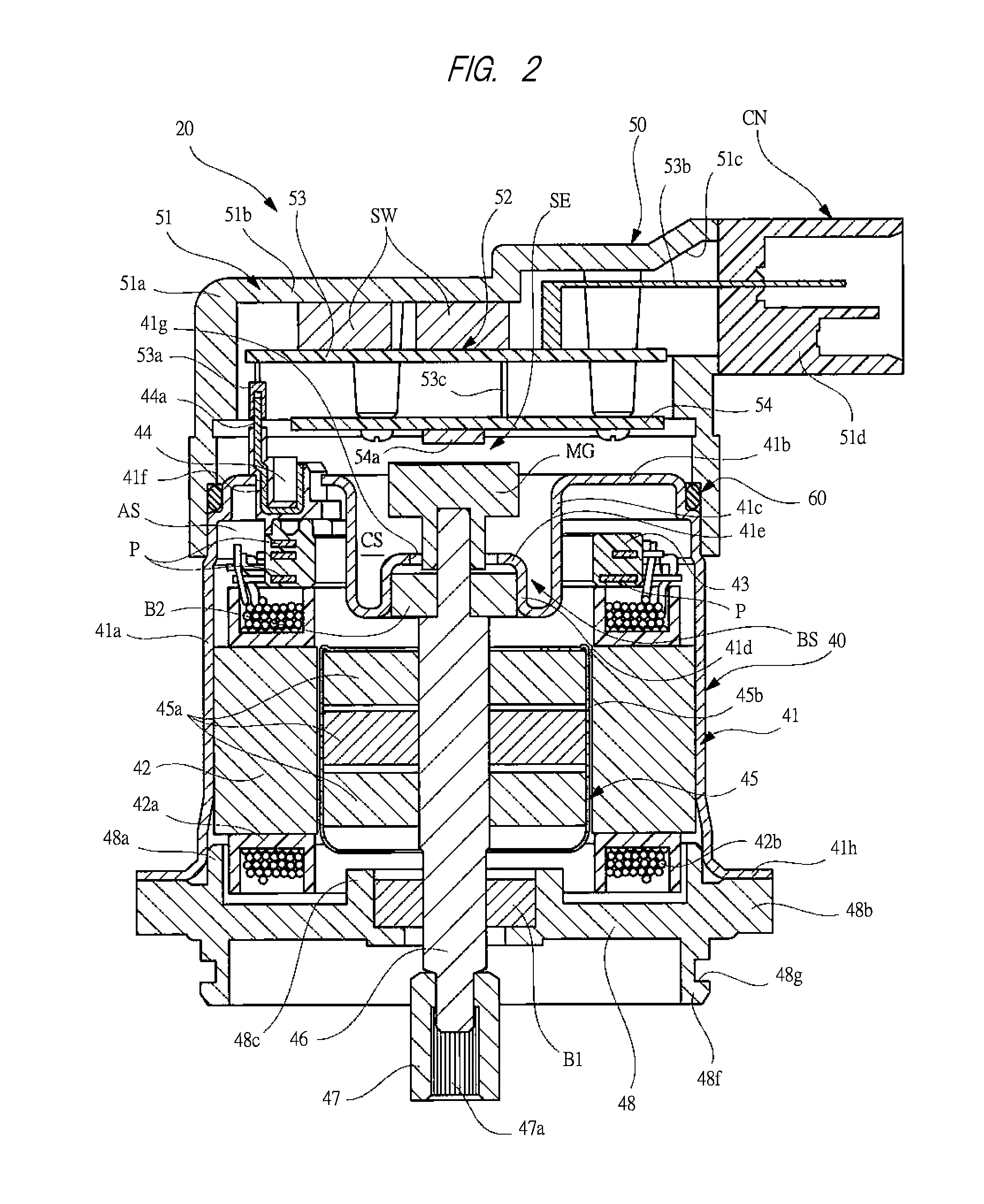
[0032]FIG. 1 is a schematic view explaining an electric power steering apparatus provided with a brushless motor according to one embodiment of the present invention, FIG. 2 is a cross sectional view showing a detail structure of the brushless motor shown in FIG. 1, FIG. 3 is an exploded perspective view showing the brushless motor shown in FIG. 1, FIG. 4 is a view for explaining a procedure for fastening a motor case side securing portion with a motor case, FIG. 5 is a partially enlarged cross sectional view showing a portion for connecting a housing member to the motor case, FIG. 6 is an enlarged cross sectional view of a portion “A” bounded by a dashed circle shown in FIG. 5, and FIG. 7 is a view for explaining a procedure for coupling the housing member with the motor case.

[0033]As shown in FIG. 1, in a body (not shown) of a vehicle such as an automobile, an elec...


PUM


Abstract

A brushless motor includes: a motor case 41 in which a cylindrical stator core 42 formed from steel plate by press molding is secured; a bracket 48 on one side in an axial direction of a motor case, a tip side of a rotary shaft 46 secured to a rotor 45 being rotatably supported by the bracket; and a housing member 51 on the other side in the axial direction of the motor case, a control device 52 for controlling the rotation of the rotor being accommodated in the housing member, the control device having a power-related circuit board 53 disposed on the side of a bottom 51b of the housing member and a control-related circuit board 54 disposed on the side of an opening of the housing member, semiconductor switching devices SW being disposed on the power-related circuit board in contact with the housing member.

Description

CROSS-REFERENCE TO RELATED APPLICATION[0001]The present application claims priority from Japanese Patent Application No. 2011-231652 filed on Oct. 21, 2011, the content of which is hereby incorporated by reference into this application.TECHNICAL FIELD OF THE INVENTION[0002]The present invention relates to a brushless motor having a stator core and a rotor that rotates in the stator core, and more particularly to a brushless motor suitable as an in-vehicle driving source.BACKGROUND OF THE INVENTION[0003]Conventionally, an electric power steering apparatus (EPS) is mounted on a vehicle such as an automotive vehicle, and this electric power steering apparatus is adapted to assist a steering operation of a steering wheel by a driver. In the electric power steering apparatus, a brushless motor superior in controlled performance is adopted as a driving source, and as a result, by controlling the brushless motor in forward / backward directions with high precision in accordance with a steeri...

Claims


Application Information

Patent Timeline
IPC IPC(8): H02K5/22H02K11/00
CPCH02K11/0068H02K5/10H02K29/08H02K11/0073H02K11/30H02K11/33
Inventor IKENO, HIROTATSUOKAMOTO, ATSUSHIOGAWA, YUYA
Owner MITSUBA CORP
Why Eureka
Try Eureka