LED current control

a current control and current technology, applied in the direction of electroluminescent light sources, electric lighting sources, semiconductor lamp usage, etc., can solve the problems of low yield and increased cost, obsolete resistor biased drive solutions, and inability to control a large number of strings, etc., to achieve cost efficiency

Active Publication Date: 2013-04-25
ALPHA & OMEGA SEMICON INC
View PDF23 Cites 28 Cited by
  • Summary
  • Abstract
  • Description
  • Claims
  • Application Information

AI Technical Summary

Benefits of technology

[0039]Embodiments of the present invention are not limited to implementations that utilize a boost converter. In alternative embodiments, a single buck converter may be used in an LED drive to step down an input voltage. By way of example

Problems solved by technology

However, manufacturing variations in forward voltage drop, luminous flux output, and/or peak wavelength may necessitate binning strategies, which may result in relatively lower yield and increased cost.
Dimming requirements and the need for circuit compensation techniques to regulate light

Method used


Image

  • LED current control
  • LED current control
  • LED current control

Examples


embodiment

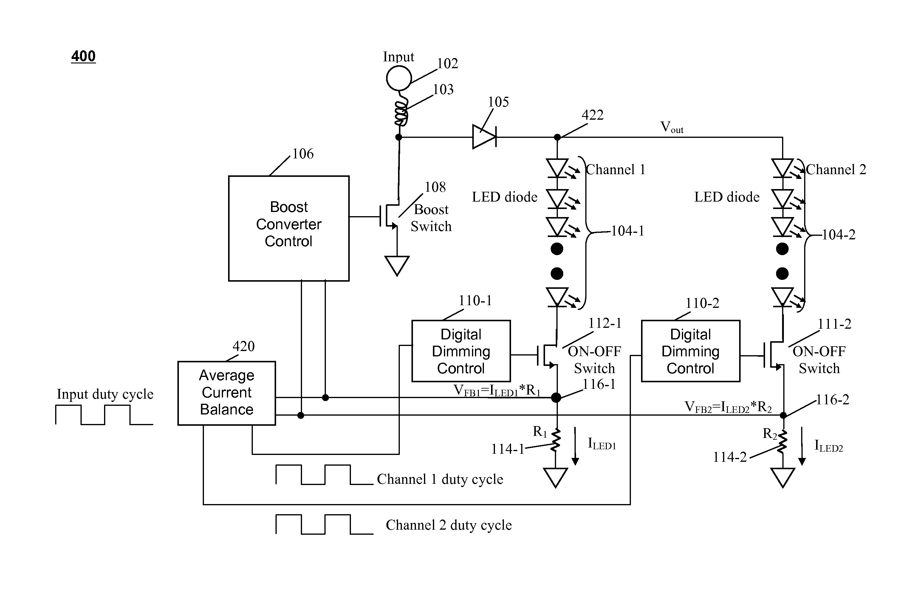
[0029]FIG. 4 is a schematic diagram of a system 400 capable of regulating multiple channels of LEDs with a single boost converter, resulting in cost efficiency, according to an embodiment of the present invention.

[0030]In the system 400 multiple parallel channels of LEDs may be coupled to the power source 102 via a Schottky diode 105 and inductor 103. The voltage across each channel is the output voltage Vout at the cathode of the Schottky diode 105. In the example, depicted in FIG. 4, two LED channels 104-1, 104-2 are shown; however, embodiments of the invention may be implemented with any number of LED channels. The voltage drop across each individual LED channel may vary with the individual characteristics of the LEDs, such that the different LED channels may have different activation voltages. For simplicity, system 400 only shows two channels of LEDs 104-1 and 104-2. The power source 102 also is coupled to a Boost Converter Control 106 through a boost switch 108. Similar to sys...


PUM


Abstract

Parallel light emitting diode channels may be controlled using a pulsed control signal input characterized by an input duty cycle and one or more current sense input signals. Each of the one or more current sense input signals is indicative of a current through a corresponding load channel of one or more load channels. One or more pulsed channel current control signals are provided to one or more corresponding dimming controls correspondingly coupled to the one or more load channels. Each of the dimming controls is configured to provide an output signal to a corresponding ON-OFF switch, each of which is coupled in series with a corresponding the load channels. The channel duty cycle of each channel current control signal is adjusted relative to the input duty cycle in response to the current sense input signals.

Description

FIELD OF THE INVENTION[0001]This invention relates in general to controlling multiple channels of light emitting diodes (LEDs) and in particular to the boost converter to drive multiple channels of LEDs using average current balance.BACKGROUND OF THE INVENTIONS[0002]Increasingly, many industrial, commercial, and public infrastructure applications have utilized light emitting diodes for lighting. Compared with previous lighting techniques such as incandescent or fluorescent lighting, LEDs can provide, a broad color spectrum, compact size, increased energy efficiency, absence of mercury and related environmental concerns, increased operating life, ability to dim output, absence of infrared or ultraviolet spectral components (when desired), and low voltage (on a per LED basis).[0003]The emergence of high brightness light emitting diodes (HB-LEDs) may have improved aspects of solid state lighting solutions, which may provide performance advantages over conventional lighting technology. ...

Claims


Application Information

Patent Timeline
IPC IPC(8): H05B37/02H05B44/00
CPCH05B33/0818Y02B20/347H05B33/0827H05B45/46Y02B20/30H05B45/38H05B45/375
Inventor CHENG, WAI-KEUNGTRAN, SON
Owner ALPHA & OMEGA SEMICON INC
Why Eureka
Try Eureka