Analog-Digital Conversion System Comprising a Double Automatic Gain Control Loop
a conversion system and automatic control technology, applied in the direction of pulse technique, instruments, transmission monitoring, etc., can solve the problems of continuous narrowband interference, limited loss introduced by digitization, interference that continuously affects a portion of the band occupied, etc., and achieve the effect of increasing weigh
- Summary
- Abstract
- Description
- Claims
- Application Information
AI Technical Summary
Benefits of technology
Problems solved by technology
Method used
Image
Examples
first embodiment
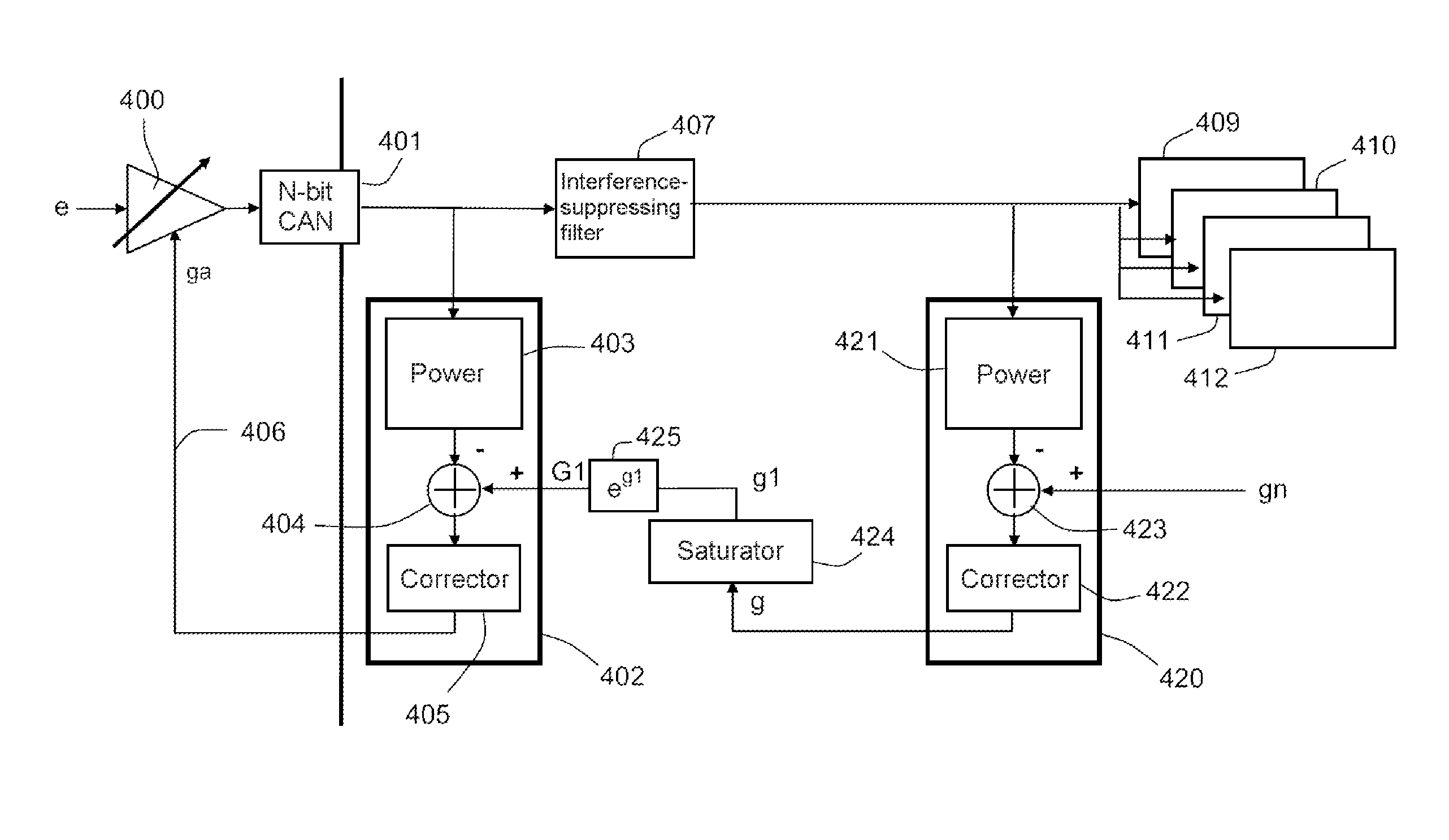
[0050]FIG. 4 shows the analog-digital conversion system according to the invention. The system consists of a transmission chain comprising an analog stage itself consisting of a variable gain amplifier 400. The object of this amplifier is to amplify an analog input signal e. After amplification, the signal is processed by a CAN converter 401 on N bits. The digitized signal at the output of the converter 401 is filtered with the aid of an interference-suppressing digital filter 407. The signal is then used to demodulate the received communication channel(s) 409, 410, 411, 412.
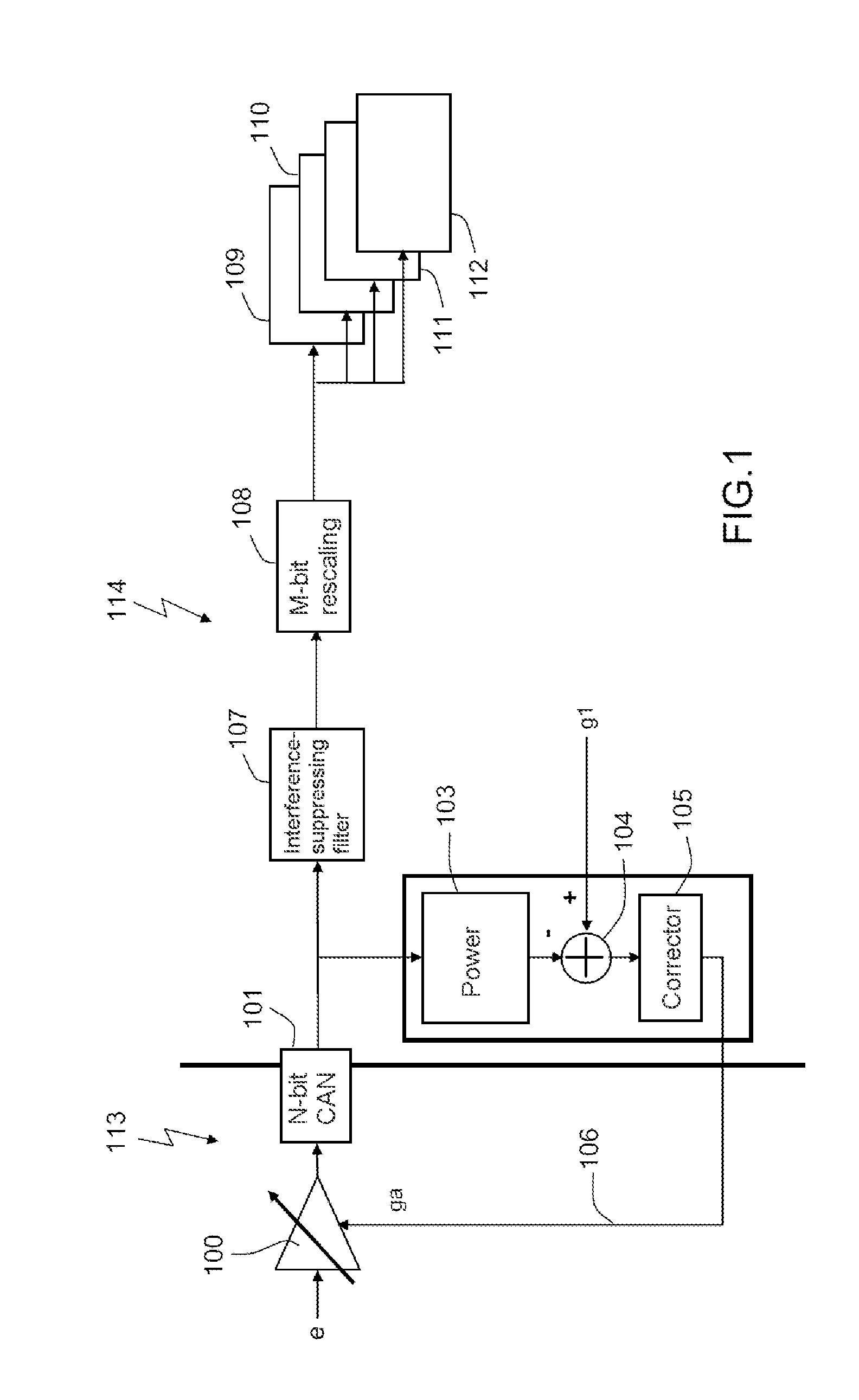
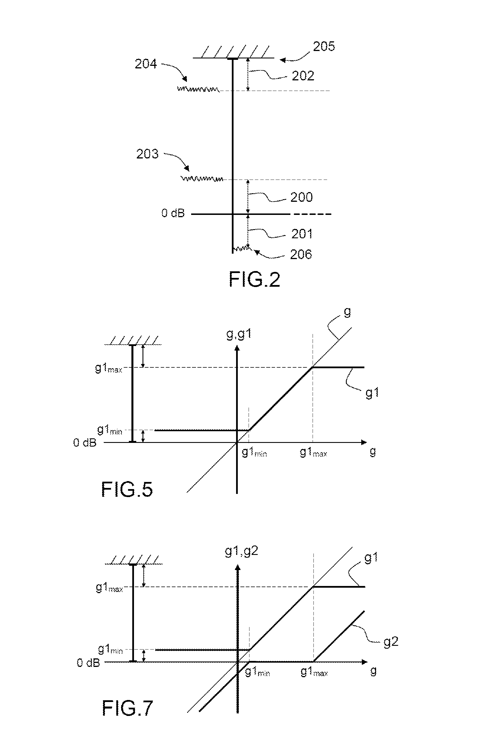
[0051]The analog-digital conversion system according to the invention uses two AGC loops 402, 420 in cascade. The first AGC loop 402 is a conventional analog AGC loop based on an estimate of power at the output of the CAN converter 401. The second AGC loop 420 is called a digital AGC loop based on an estimate of power at the output of the interference-suppressing filter 407 and of which the object is to determin...
second embodiment
[0062]FIG. 6 shows the analog-digital conversion system according to the invention. The system consists of a transmission chain comprising an analog stage itself consisting of at least one variable gain amplifier 600. The object of this amplifier is to amplify an analog input signal e. After amplification, the signal is processed by a CAN converter 601 on N bits. The digitized signal at the output of the converter 601 is filtered with the aid of an interference-suppressing digital filter 602. The bits at the output of the filter are rescaled on M bits by a rescaling module 603. The digitized and rescaled signal is then used to demodulate 606, 607, 608, 609 the received communication channel(s).
[0063]As for the first embodiment, two AGC loops 604, 605 in cascade are also used. The first AGC loop 604 is a conventional analog AGC loop based on an estimate of the power at the output of the CAN converter 601. The second AGC loop 605 is a digital AGC loop based on an estimate of the power...
third embodiment
[0069]FIG. 8 shows the analog-digital conversion system according to the invention. The system consists of a transmission chain comprising an analog stage itself consisting of a variable gain amplifier 800. The objective of this amplifier is to amplify an analog input signal e. After amplification, the signal is processed by a CAN converter 801 on N bits. The digitized signal at the output of the converter 801 is filtered with the aid of an interference-suppressing digital filter 802. The bits at the output of the filter are rescaled 803 on M bits. The digitized and rescaled signal is then used to demodulate 806, 807, 808, 809 the received communication channel(s).
[0070]As for the first two embodiments, two AGC loops 804, 805 in cascade are used. The first AGC loop 804 is a conventional analog AGC loop based on the output of the CAN converter 801. The second AGC loop 805 is a digital AGC loop based on the output of the interference-suppressing filter 802. A saturation module 810 ded...
PUM
 Abstract
Description
Claims
Application Information
 - R&D
- Intellectual Property
- Life Sciences
- Materials
- Tech Scout
- Unparalleled Data Quality
- Higher Quality Content
- 60% Fewer Hallucinations
Browse by: Latest US Patents, China's latest patents, Technical Efficacy Thesaurus, Application Domain, Technology Topic, Popular Technical Reports.
© 2025 PatSnap. All rights reserved.Legal|Privacy policy|Modern Slavery Act Transparency Statement|Sitemap|About US| Contact US: help@patsnap.com


