High speed high resolution wide range low power analog correlator and radar sensor

a low-power, analog correlator technology, applied in the field of radar sensors, can solve the problems of deteriorating the signal-to-noise ratio (snr) of the receiver difficult and/or cost-inefficient for conventional radar sensors to achieve high resolution, and high thermal noise in wideband signals, so as to improve the dynamic range of the conventional radar sensor, improve the detection speed of the conventional analog correlator, and improve the effect of high speed

Inactive Publication Date: 2013-04-25
PANASONIC CORP
View PDF11 Cites 20 Cited by
  • Summary
  • Abstract
  • Description
  • Claims
  • Application Information

AI Technical Summary

Benefits of technology

[0009]The present invention can enable various improved analog correlators. In return the improved analog correlators can enable various improved radar sensors. The improved analog correlators can combine various transmission pulse replication schemes with various parallel integrator architectures to improve the detection speed of conventional analog correlators. Moreover, the improved analog co

Problems solved by technology

Due to many design constraints, it may be difficult and/or cost inefficient for conventional radar sensors to achieve a high resolution and a high detection range at the same time.
However, these wideband signals typically have high thermal noise levels when compared to narrow band signals, which may be used in conventional radar sensors with low resolution.
The high thermal noise levels lead to the deterioration of the signal-to-noise ratio (SNR) of the receivers of the conventional radar sensors.
Due to this SNR deterioration, the conventional radar sensors may have difficulties in receiving the wideband signals reflected by remote targets.
Consequently, these conventional radar sensors may suffer from a decline in dynamic range.
However, because of the large number of bits and the high sampling frequency, the power consumption of these radar sensors

Method used


Image

  • High speed high resolution wide range low power analog correlator and radar sensor
  • High speed high resolution wide range low power analog correlator and radar sensor
  • High speed high resolution wide range low power analog correlator and radar sensor

Examples


first embodiment

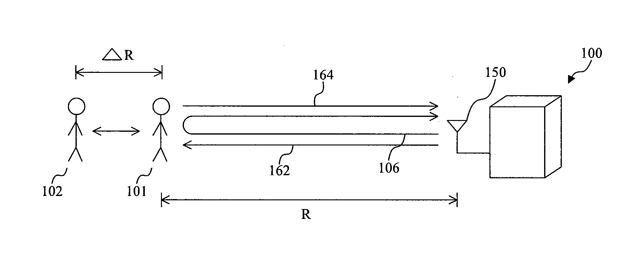
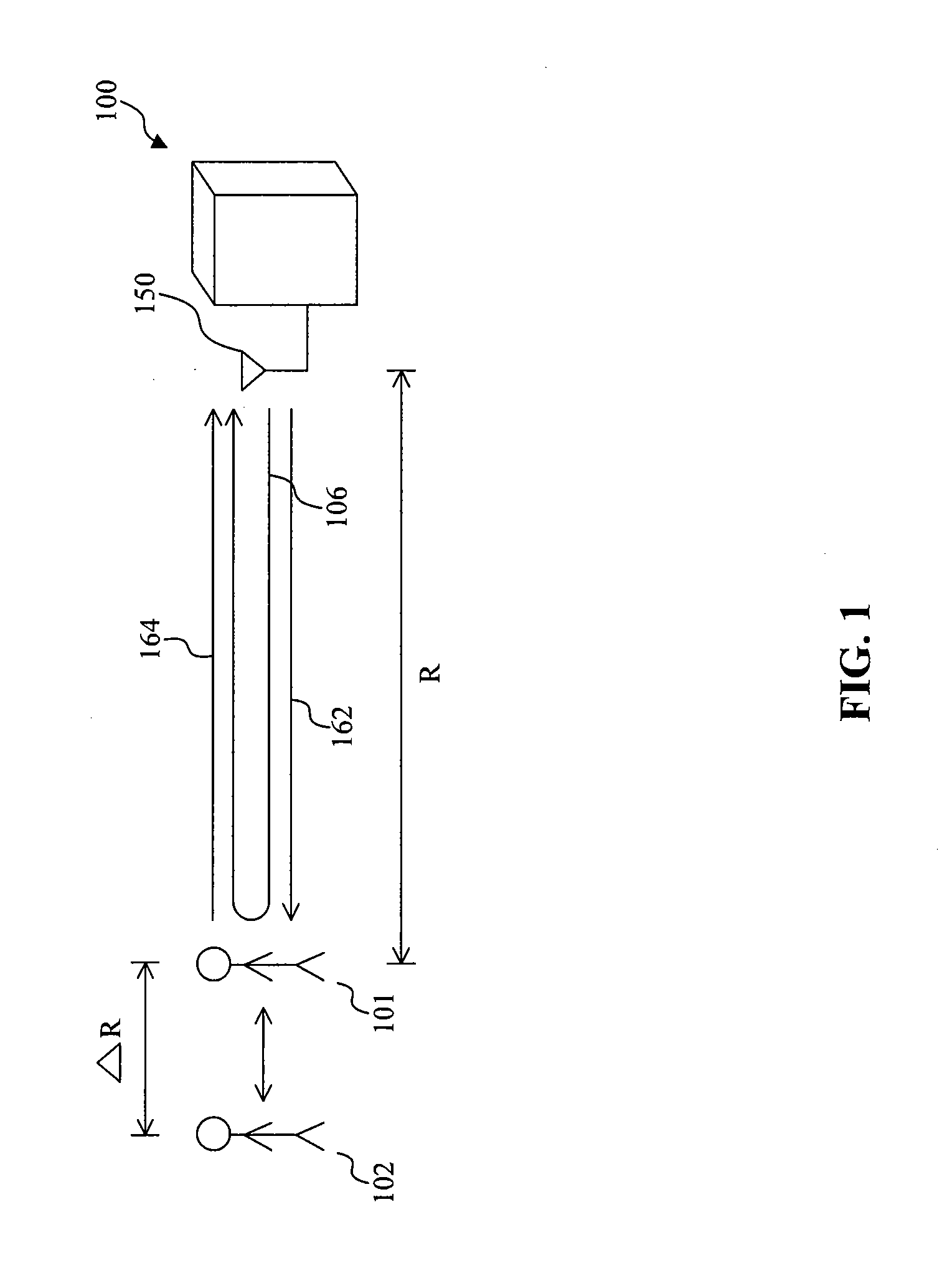
[0054]FIG. 1 shows a front view of a radar sensor 100 for measuring the positions of two targets according to the present invention. The radar sensor 100 can be part of a radar system. The radar sensor 100 has an antenna 150 for transmitting a radio frequency (RF) modulated signal 162. The transmitted RF modulated signal 162 has a carrier frequency and a code modulated message. The code modulated message can be a pulse compression radar (PCR) signal. The PCR signal can be modulated by using one or more digital modulation schemes, which may include but not be limited to, phase-shift keying (PSK), binary phase-shift keying (BPSK), frequency-shift keying (FSK), and / or amplitude-shift keying (ASK). Because of its encoded message, the transmitted RF modulated signal 162 may also be referred to as the transmitted PCR signal 162.

[0055]The transmitted PCR signal 162 will travel a distance R until it reaches a first target at a first position 101. The first target will then reflect the trans...

second embodiment

[0133]FIG. 9 shows a schematic view of a radar sensor 900 according to the present invention. The radar sensor 900 can be incorporated in a radar system. The radar sensor 900 includes a PCR signal generator 932, an analog correlator module 910, a detection controller 930, an RF front end module 940, and an antenna module 950. The analog correlator module 910 communicates and cooperates with the detection controller 930 in detecting the positions of one or more targets. From a high level stand point, the analog correlator module 910 performs similar functions as the analog correlator 110, while the detection controller 930 performs similar functions as the detection controller 130.

[0134]At the beginning of a detection cycle, the detection controller 930 generates a detection cycle signal 935, which causes the PCR signal generator 932 to generate an initial PCR signal 933. The initial PCR signal 933 includes a PCR pulse having a PCR pulse width TP and a compressed code sequence. The c...

third embodiment

[0175]FIG. 12 shows a schematic view of a high speed radar sensor 1200 according to the present invention. When compared to the radar sensor 900, the high speed radar sensor 1200 includes several modifications. For example, the analog correlator module 910 is replaced by the analog correlator module 1210, which incorporates a parallel architecture for fast target detection. In the parallel architecture, the integrator module 960 is replaced by an integrator bank 1250. The integrator bank 1250 processes multiple correlations at several periods of time, such that the number of detection cycles and the overall detection time is reduced geometrically. The integrator bank 1250 may include two or more parallel integrator modules, such as a first integrator module 1260 and a second integrator module 1280. Each of the first integrator module 1260 and the second integrator module 1280 may include similar structural and functional features as the integrator module 960.

[0176]In one embodiment,...


PUM


Abstract

Systems, methods and apparatus related to a high speed, high dynamic range and low power consumption radar system are provided herein. The radar system may include an analog correlator which combines various pulse replication schemes with various parallel integrator architectures to improve the detection speed, dynamic range, and power consumption of conventional radar sensors. The radar system may further include a matched filter for determining a match of a portion of a received PCR signal and producing an output signal in response to further improve the speed of detection of the radar system.

Description

BACKGROUND OF THE INVENTION[0001]1. Field of the Invention[0002]The present invention relates generally to the field of radar sensors and more particularly to high speed high resolution wide range and low power analog correlators and radar sensors that incorporate the same.[0003]2. Description of Related Art[0004]Conventional radar sensors are widely used in detecting the positions of one or more targets. These conventional radar sensors may have various detection range capabilities. Generally, the detection range of high resolution radar sensors may be shorter than the detection range of low resolution radar sensors. Due to many design constraints, it may be difficult and / or cost inefficient for conventional radar sensors to achieve a high resolution and a high detection range at the same time.[0005]For example, attempts have been made in using wideband signals to improve the resolution of the conventional radar sensors. However, these wideband signals typically have high thermal n...

Claims


Application Information

Patent Timeline
IPC IPC(8): G01S13/00
CPCG01S7/292G01S7/282G01S13/284G01S7/2886
Inventor MATSUO, MICHIAKI
Owner PANASONIC CORP
Why Eureka
Try Eureka