
Small molecules and protein analysis devices based on molecular imprinted polymers

a technology of imprinted polymers and small molecules, applied in the field of diagnostics, can solve the problems of cumbersome sample preparation, background art methods that do not disclose the use of mips in flow through or lateral flow devices, etc., and achieves the effects of strong and/or stable visual signals, rapid and simple assays, and improved sensitivity

Inactive Publication Date: 2013-04-25
LEVI RAFAEL +2
View PDF4 Cites 15 Cited by
  • Summary
  • Abstract
  • Description
  • Claims
  • Application Information

AI Technical Summary

Benefits of technology

Enables real-time, portable, and cost-effective detection of small molecules, proteins, cells, and infectious agents in liquid samples, providing stronger visual signals and reduced indeterminate results, suitable for use by untrained personnel in various settings, including field conditions.

Problems solved by technology

The background art does not disclose the use of MIPs in a flow through or lateral flow device.
Furthermore, the background art methods involve cumbersome sample preparation, and require use of sophisticated auxiliary analytical instrumentation by trained personnel.

Method used


Image

  • Small molecules and protein analysis devices based on molecular imprinted polymers
  • Small molecules and protein analysis devices based on molecular imprinted polymers
  • Small molecules and protein analysis devices based on molecular imprinted polymers

Examples


example i

Embodiment of FIG. 1A

[0158]There is described below the structure and operation of a lateral flow device with competition or single displacement and vertical visualization.

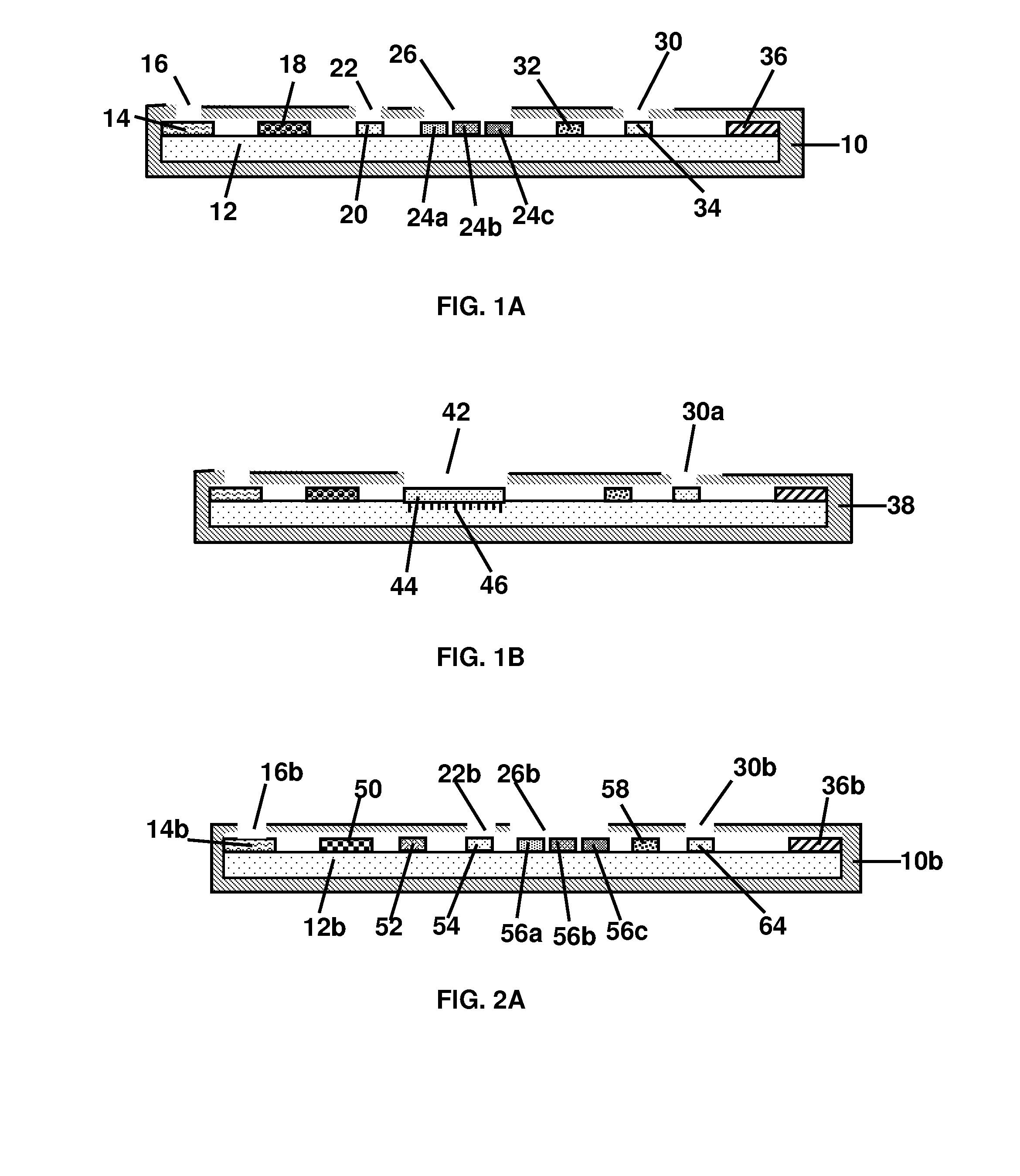
[0159]FIG. 1A is a side view illustration of a lateral flow device for detecting and determining the presence, absence or concentration of a target analyte present in a liquid sample. The analytical test device comprises a hollow, solid casing 10 that contains a solid support 12 in the form of a porous test strip that serves as a carrier capable of conveying a liquid sample therethrough, the sample being movable along the solid support in the path of liquid flow by capillary action. The solid support 12 has defined zones, including a sample application area comprising a sample application pad 14 for applying the sample to the device and bringing it in contact with the solid support 12. The sample application pad 14 is located adjacent to an opening or window 16 in the casing 10 for applying the liquid sample. When...

example 2

Embodiment of FIG. 1B

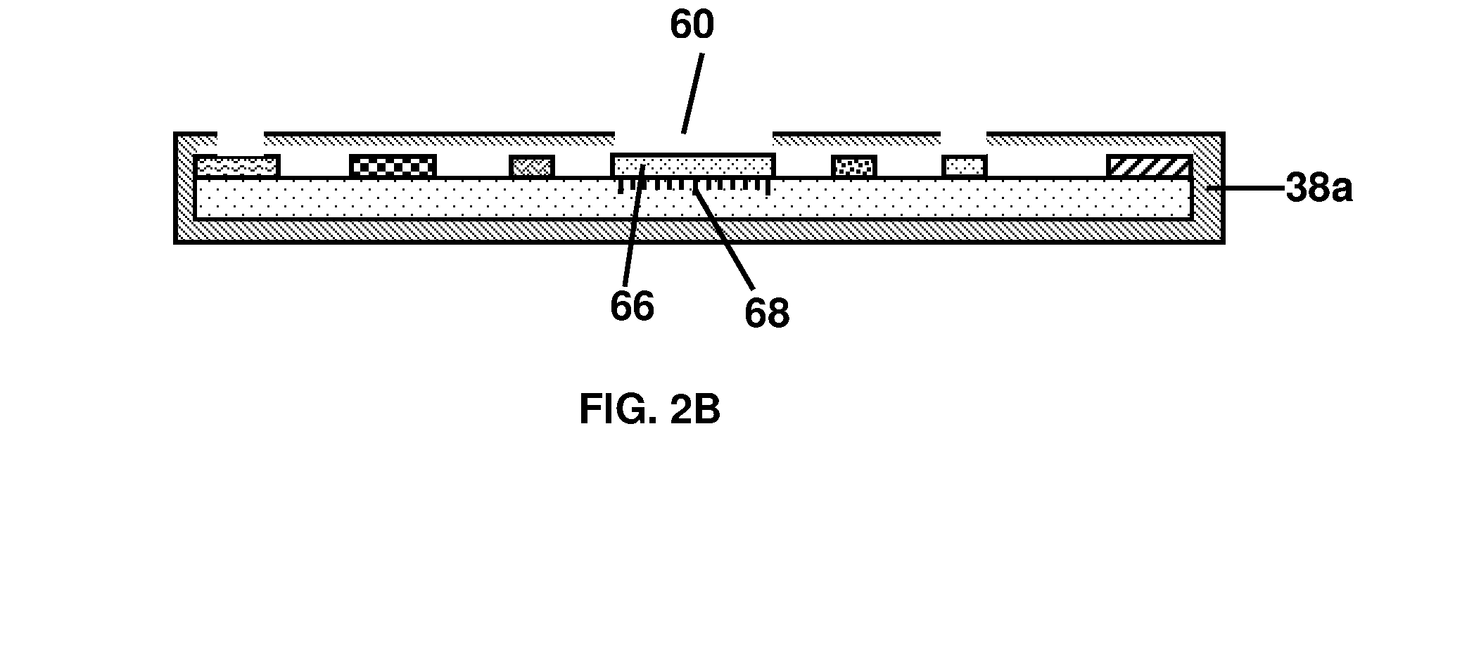
[0165]There is described below the structure and operation of a lateral flow device with competition or single displacement and horizontal visualization of the test results.

[0166]The lateral flow device is the same as that described above in Example 1, with similar numerals designating similar parts except that modifications are indicated with the reference numeral and the letter “a” affixed. The modifications are as follows: There is no reference zone in the device of FIG. 1B, thus, the casing 38 has fewer windows or openings, and has an enlarged results window 42. Results are read only from the results window 42 according to the distance that the analyte analog:reporter conjugate covered. The area covered by the immobilized analyte analog:reporter conjugate binding element 44 is enlarged with a scale 46 running parallel to it. The scale 46 and the area covered by the immobilized analyte analog:reporter conjugate binding element 44 are co-calibrated to correspo...

example 3

Embodiment of FIG. 2A

[0167]There is described below the structure and operation of a lateral flow device with competition / double displacement and vertical visualization of the test results.

[0168]FIG. 2A is a side view illustration of a lateral flow device for detecting and determining the presence, absence or concentration of a target analyte present in a liquid sample. The device comprises a hollow, solid casing 10b that contains a solid porous support 12b in the form of a test strip capable of conveying a liquid sample therethrough, the sample being movable along the solid support in the path of liquid flow by capillary action. The solid support 12b has defined zones, including a sample to application area comprising a sample application pad 14b for applying the sample to the device and bringing it in contact with the solid support 12b. The sample application pad 14b is located adjacent to an opening or window 16b in the casing 10b for applying the liquid sample. When competition ...


PUM

PropertyMeasurementUnit
displacementaaaaaaaaaa
areaaaaaaaaaaa
affinityaaaaaaaaaa

Abstract

Devices, methods and kits for rapid and simple determination of target molecules, including small molecules, polypeptides, proteins, cells and infectious disease agents in liquid samples that are capable of real-time measurement of these entities in fluid samples that are highly selective, highly sensitive, simple to operate, low cost, and portable. The devices, methods and kits also provide, in at least some embodiments, the use of MIPs in a flow through or lateral flow device.

Description

[0001]This application is a continuation of U.S. application Ser. No. 12 / 318,378, filed on Dec. 29, 2008, which is a continuation in part of PCT Application No. PCT / IL2007 / 00789 filed on Jul. 8, 2007 which claims priority from U.S. Provisional Application No. 60 / 806,783, filed on Jul. 9, 2006; and which further claims priority from U.S. Provisional Application 61 / 016,829, filed Dec. 27, 2007, and U.S. Provisional Application 61 / 027,462, filed Feb. 10, 2008, all of which are hereby incorporated by reference as if fully set forth herein.FIELD OF THE INVENTION[0002]The present invention relates to the field of diagnostics, and more particularly to flow through or lateral flow devices based on the use of molecularly imprinted polymers for measurement of analyte levels in a liquid sample, and methods and kits for use thereof.BACKGROUND OF THE INVENTION[0003]Methods and devices for efficient and accurate detection and quantification of the level of analytes, such as protein related analyt...

Claims


Application Information

Patent Timeline
Patent Type & Authority Applications(United States)
IPC IPC(8): G01N33/53
CPCG01N33/54386G01N33/5302G01N33/558G01N33/54388
Inventor LEVI, RAFAELMARGALIT, IDODLOOMY, YARDEN
Owner LEVI RAFAEL
Learn More