
Components of plasma processing chambers having textured plasma resistant coatings

a technology of plasma processing chamber and coating, which is applied in the direction of transportation and packaging, combustion types, lighting and heating apparatus, etc., can solve the problems of difficult to correctly unfavorable temperature increase of adjacent components, and difficult to properly reseal the upper chamber section after maintenan

Inactive Publication Date: 2013-04-25
LAM RES CORP
View PDF9 Cites 20 Cited by
  • Summary
  • Abstract
  • Description
  • Claims
  • Application Information

AI Technical Summary

Benefits of technology

This patent is about a component of a plasma processing chamber that has a special coating on it. This coating helps prevent particles from accumulating on the surface of the chamber and causing issues during processing. The coating is 10 to 60 microns thick and is made of yttria with a high degree of purity. It has a unique texture that includes small scratches and smooth areas. The purpose of this coating is to improve the efficiency and reliability of plasma processing chambers.

Problems solved by technology

Cleaning is problematic in that the ceramic coatings of this type are easily damaged and due to the sensitive processing of some plasma processes, it is sometimes preferred to replace the upper chamber section rather than remove it for cleaning.
In addition, correctly reseating the upper chamber section after maintenance is often difficult, since it must properly be aligned with the bottom chamber section such that a set of gaskets properly seal around the upper chamber section.
However, plasma processing may require temperature changes during multi-step processing and it may be necessary to heat the upper chamber section to temperatures above 100° C., e.g. 120, 130, 140, 150 or 160° C. or any temperature therebetween whereas the prior upper chamber sections were run at much lower temperatures on the order of 60° C. The higher temperatures can cause undesirable increases in temperature of adjacent components such as the bottom chamber section.
Thus, heat flow variations originating from the upper chamber section may cause the substrate temperature to vary outside narrow recipe parameters.

Method used


Image

  • Components of plasma processing chambers having textured plasma resistant coatings
  • Components of plasma processing chambers having textured plasma resistant coatings
  • Components of plasma processing chambers having textured plasma resistant coatings

Examples


Embodiment Construction

[0017]The present invention will now be described in detail with reference to a few preferred embodiments thereof as illustrated in the accompanying drawings. In the following description, numerous specific details are set forth in order to provide a thorough understanding of the present invention. It will be apparent, however, to one skilled in the art, that the present invention may be practiced without some or all of these specific details. In other instances, well known process steps and / or structures have not been described in detail in order to not unnecessarily obscure the present invention. As used herein, the term “about” should be construed to include values up to 10% above or below the values recited.

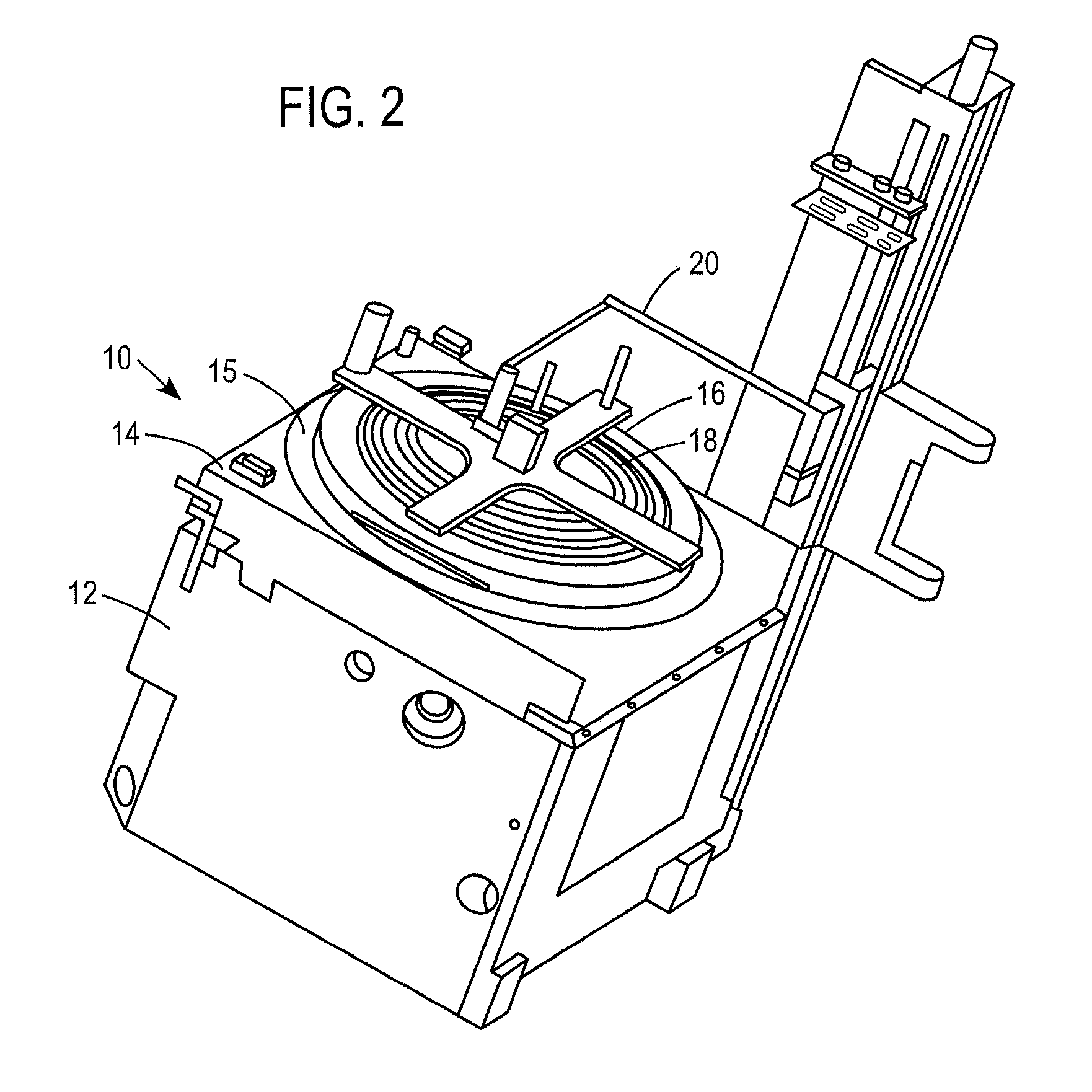
[0018]Described herein are components of a plasma chamber such as that illustrated in FIG. 2. The components include a ceramic window and gas injector which mounts in an opening in the window.

[0019]The plasma system shown in FIG. 2 includes a chamber 10 which includes a lower...


PUM

PropertyMeasurementUnit
depthaaaaaaaaaa
thicknessaaaaaaaaaa
Raaaaaaaaaaa

Abstract

A component of a plasma processing chamber includes a three dimensional body having a highly dense plasma resistant coating thereon wherein a plasma exposed surface of the coating has a texture which inhibits particle generation from film buildup on the plasma exposed surface. The component can be a window of an inductively coupled plasma reactor wherein the window includes a textured yttria coating. The texture can be provided by contacting the plasma exposed surface with a polishing pad having a grit size effective to provide intersecting scratches with a depth of 1 to 2 microns.

Description

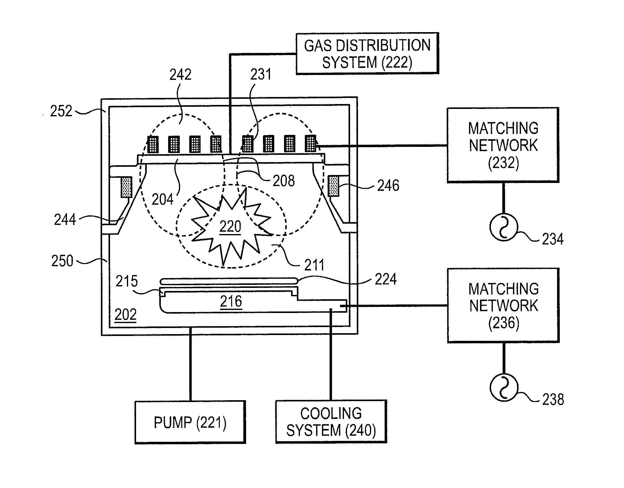
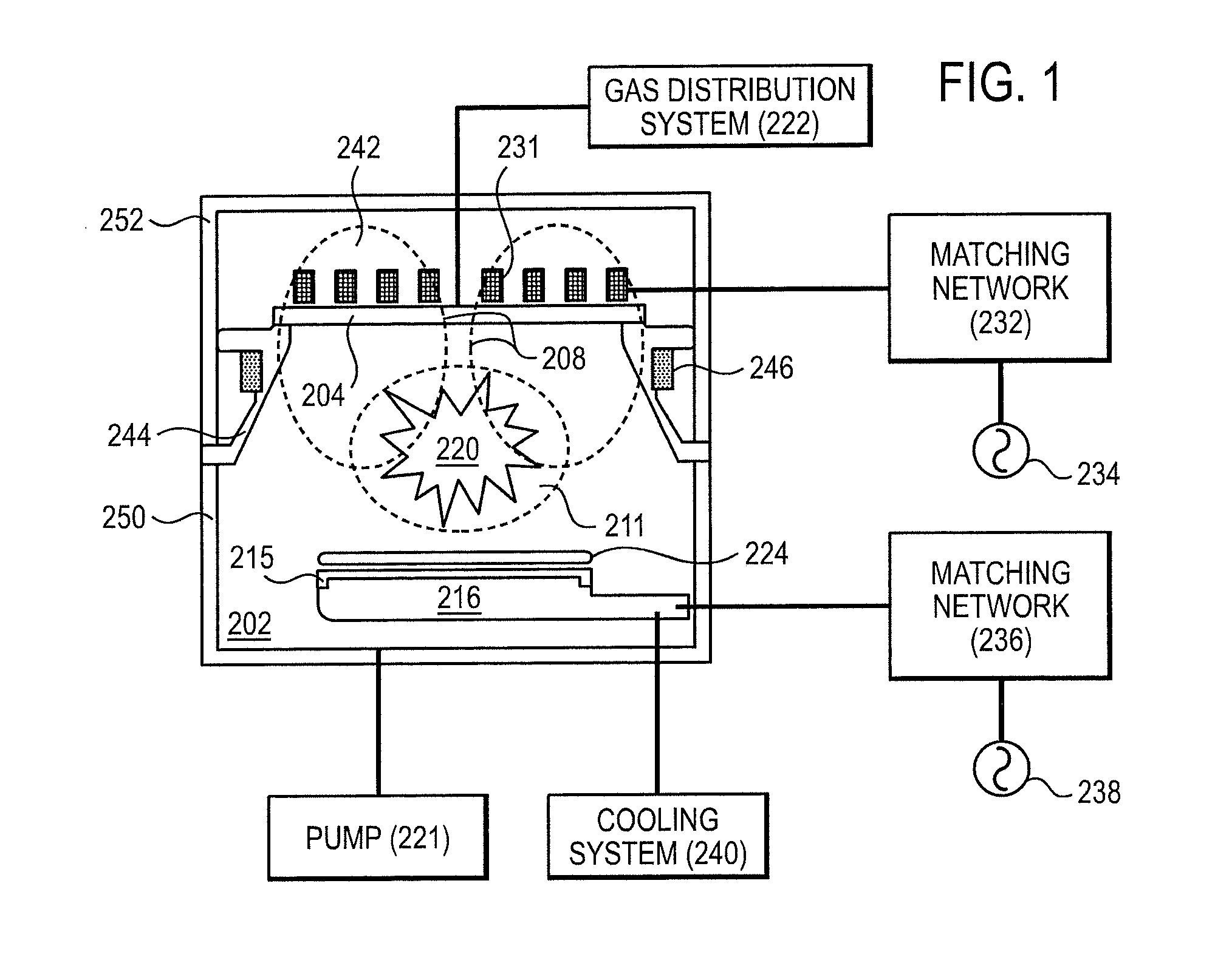
CROSS REFERENCE TO RELATED APPLICATION[0001]This application claims priority under 35 U.S.C. §119(e) to U.S. Provisional Application No. 61 / 549,895, filed on Oct. 21, 2011, the entire content of which is incorporated herein by reference thereto.BACKGROUND[0002]The invention relates to components of a plasma processing chamber in which semiconductor substrates are processed.[0003]Referring now to FIG. 1, a simplified diagram of inductively coupled plasma processing system components is shown. Generally, the plasma chamber (chamber) 202 is comprised of a bottom chamber section 250 forming a sidewall of the chamber, an upper chamber section 244 also forming a sidewall of the chamber, and a cover 252. An appropriate set of gases is flowed into chamber 202 from gas distribution system 222. These plasma processing gases may be subsequently ionized to form a plasma 220, in order to process (e.g., etch or deposition) exposed areas of substrate 224, such as a semiconductor substrate or a gla...

Claims


Application Information

Patent Timeline
Patent Type & Authority Applications(United States)
IPC IPC(8): B05B1/00B32B3/02H01L21/3065B32B3/30B05D3/12C23C16/44
CPCB05B1/00B32B3/02B32B3/30Y10T428/24471H01L21/3065H01J37/32477Y10T428/218C23C16/44H01J37/32119
Inventor STEVENSON, TOMSHIH, HONGO'NEILL, ROBERT G.KIM, TAE WONCASAES, RAPHAELFANG, YAN
Owner LAM RES CORP
Learn More