Applicators for storing sterilizing, and dispensing an adhesive

a technology of sterilizing and adhesives, applied in the direction of rigid containers, pliable tubular containers, transportation and packaging, etc., can solve the problems of clogging the applicator tip, exposing the user or patient to risk, waste of adhesive materials, etc., and achieves the effect of safe and efficient use and convenient us

Active Publication Date: 2013-05-02
ADHEZION BIOMEDICAL
View PDF2 Cites 53 Cited by
  • Summary
  • Abstract
  • Description
  • Claims
  • Application Information

AI Technical Summary

Benefits of technology

[0014]This invention provides applicators which address the need for an easy to use, safe and efficient package system for applying and dispensing an adhesive material. Various applicators disclosed herein are designed to ...

Problems solved by technology

The breakage or rupture of broken glass through the outside plastic package exposes the user or patient to risk.
Another problem associated with this type of applicator is the clogging of the applicator tip.
The presence of polymerization initiator in the applicator tip can lead to rapid polymerization of cyanoacrylate adhesives to clog the applicator, which causes the waste of adhesive material.
The clogging of the applicator may delay the wound closure process during surgery, which may result in problems for both patients and surgical professionals.
The lack of flow rate control of a...

Method used


Image

  • Applicators for storing sterilizing, and dispensing an adhesive
  • Applicators for storing sterilizing, and dispensing an adhesive
  • Applicators for storing sterilizing, and dispensing an adhesive

Examples


first embodiment

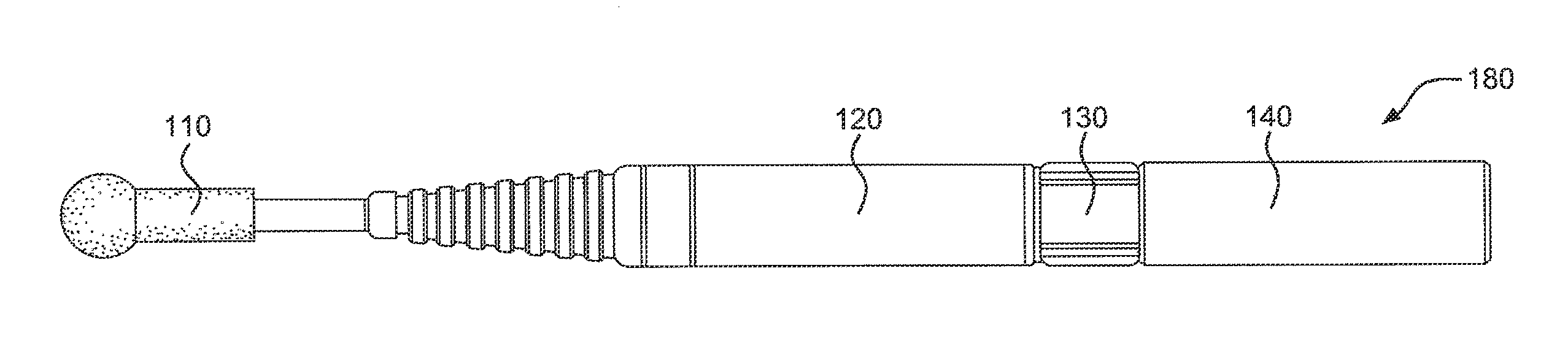
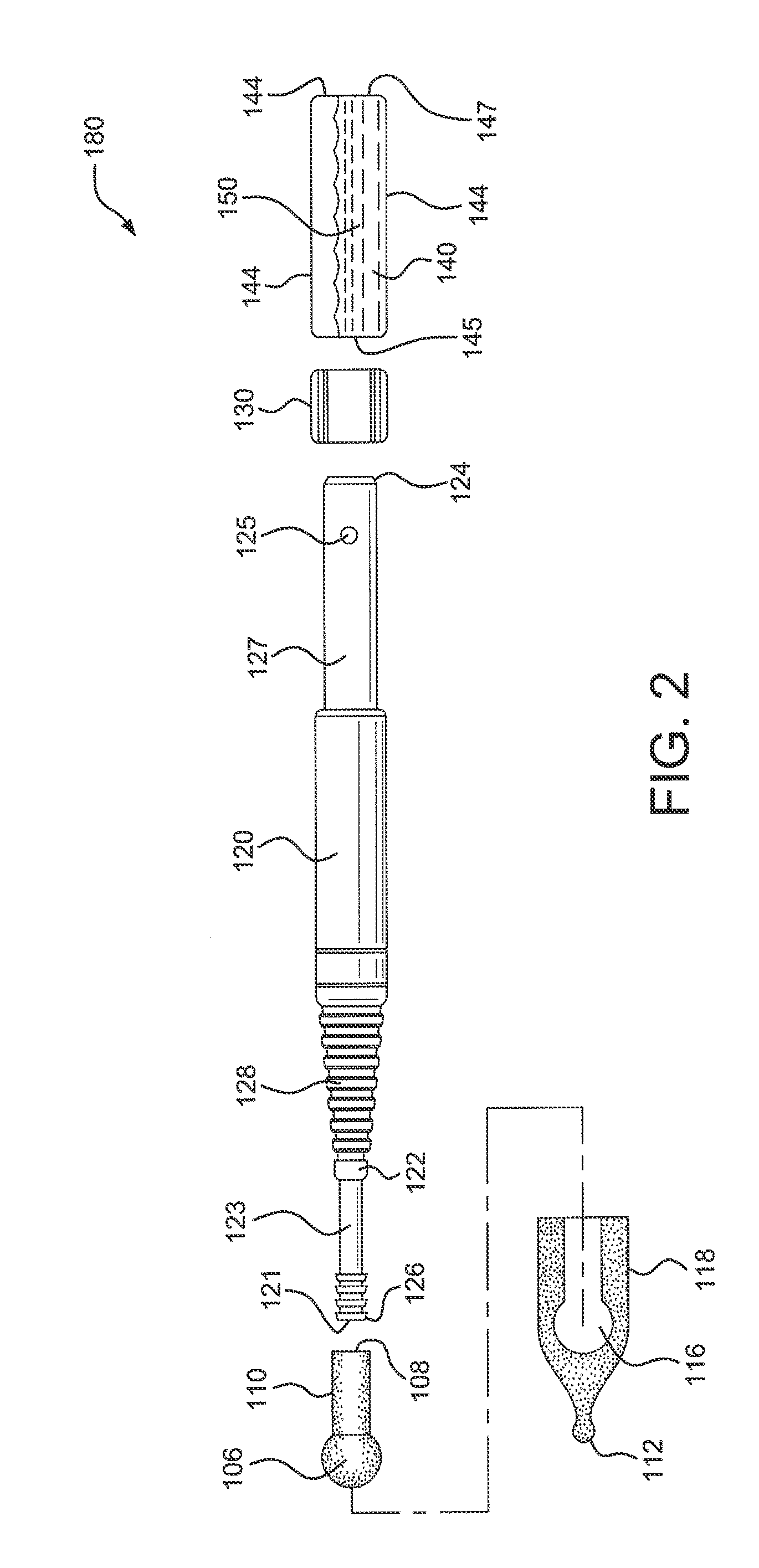
[0050]FIGS. 2 and 3 show an exploded view and a cross-sectional view of the present invention, respectively. The applicator body 120 has a distal end 126, and this distal end 126 can fit inside of the proximal end 108 of the applicator tip 110. The connection between the applicator tip 110 and the applicator body 120 may be, for example, a snap-lock fit, a luer lock fit, a screw-cap fit, or a friction fit, and is capable of substantially reducing, inhibiting, or preventing leaking of an adhesive 150 out from the junction of the tip 110 and body 120. The applicator body 120 may include a flow restrictor 122, a grip 128, a flange 127 which has at least one hole 125, and a channel 123 having an opening 121 at its distal end, as shown in FIGS. 2 and 3. The hole 125 and the channel 123 are in communication and serve to have access to, and as a conduit for an adhesive 150 stored in the container 140.

[0051]The container 140 comprises a plurality of walls 144 that define a chamber 149 that ...

second embodiment

[0067]FIGS. 4-6 show a perspective view, an exploded view and a cross-sectional view, respectively, of the applicator of the invention. In some aspects, an applicator 280 comprises the following basic components: an applicator tip 210, a body 220, and a handle 270. The handle 270 may, for example, include a housing 274 for holding a removable adhesive container 240.

[0068]The removable adhesive container 240 may comprise a packet or a pouch, for example, a stick pack, and may comprise a frangible seal 256 at its distal end 258, which may be in communication with or attach to a channel 223 in the body 220, as shown in the cross-sectional view in FIG. 6. The adhesive container 240 preferably contains and stores an adhesive 250.

[0069]The body 220 may be connected to the handle 270 using the male portion of a luer lock 226 on the proximal end 224 of the body 220 and the female portion of a luer lock 272 on the distal end 276 of the handle 270. The body 220 and the handle 270 preferably f...

third embodiment

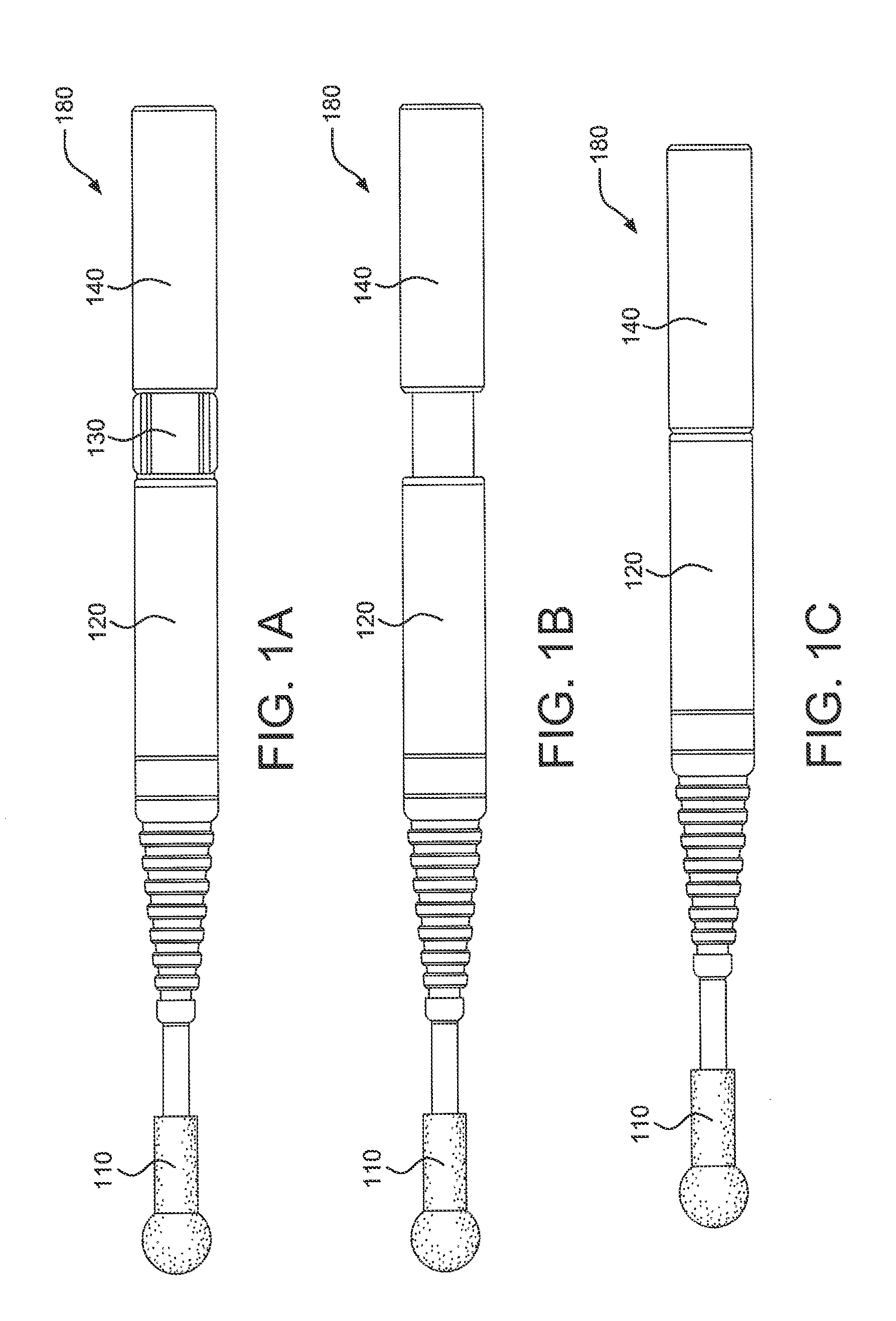
[0083]FIGS. 7-9 illustrate a perspective view, an exploded view and a cross-sectional view, respectively, of the applicator of the invention. As shown in FIG. 7, an applicator 380 according to this embodiment includes these basic components: an applicator tip 310, an applicator body 320, and a container 340. The container 340 is movable relative to the body 320, for example, by being compressed together. Optionally, a lock 330 may be placed between the applicator body 320 and the container 340.

[0084]In some aspects, the applicator body 320 comprises a distal end 326, a reservoir 322, a flange 327 which is equipped with a hole 325 and a channel 323, as shown in FIGS. 8 and 9. The hole 325 and the channel 323 are in communication for allowing an adhesive 350 to flow out from the container 340 and through the body 320 of the applicator 380.

[0085]The flange 327 of the applicator body 320 may be inserted into the distal end 345 of the container 340, for example, via a friction fit, and s...


PUM


Abstract

Applicators for storing, sterilizing, and dispensing adhesives are provided. The applicators comprise a porous tip, a body, and a container containing a polymerizable cyanoacrylate monomer adhesive. The applicators are sterilized by radiation, and following sterilization, the adhesive remains substantially unpolymerized for about twenty four months.

Description

FIELD OF INVENTION[0001]This invention relates generally to the field of adhesive applicator devices. More particularly, the invention relates to sterilizable applicators for storing and applying adhesives.BACKGROUND[0002]Various publications, including patents, published applications, technical articles and scholarly articles are cited throughout the specification. Each of these cited publications is incorporated by reference herein, in its entirety and for all purposes.[0003]A large number of dispensing and packaging systems for cyanoacrylate-based adhesive and / or sealant material have been proposed. U.S. Pat. No. 4,413,753 to Stock discloses a self-draining tip for dispensing cyanoacrylate adhesives. The dispensing tip includes a single or segmented constant diameter passageway having sharp-edged annular terminations for dispensing. U.S. Pat. No. 4,685,591 to Schaefer et al. discloses a packaging tube that is suitable for storing and dispensing products containing substantial fra...

Claims


Application Information

Patent Timeline
IPC IPC(8): B65D25/40
CPCA46B11/0075B65D35/36B65D51/225A61M35/006A61B17/00491A61M35/003A61B2019/4868A61B2090/0813B05C17/00586
Inventor RUIZ, SR., RAFAELZHANG, SHENGKRAUSS, MARTIN
Owner ADHEZION BIOMEDICAL
Why Eureka
Try Eureka