Hydraulic start/stop system

a technology of start/stop system and hydraulic pump, which is applied in the direction of engine starters, electrical control, fluid couplings, etc., can solve the problem that the torque available from the prime mover exceeds the torque required by the pump unit, and achieves the effect of saving energy, simplifying the control of the motor, and reducing the size of the components

Inactive Publication Date: 2013-05-09
PARKER HANNIFIN AB
View PDF13 Cites 18 Cited by
  • Summary
  • Abstract
  • Description
  • Claims
  • Application Information

AI Technical Summary

Benefits of technology

[0010]A proportional flow control valve is arranged to connect the motor unit to a source of low pressure, or drain. The proportional flow control valve controls the fluid flow from the accumulator through the motor and is used for controlling the speed and output torque of the motor. The flow control valve is provided with a check valve to prevent flow in the direction of the drain when the flow valve is in its non-actuated position. This prevents the motor from being operated during charging of the accumulator.
[0024]The fluid system and method described above will make it possible to save energy by shutting down prime movers such as internal combustion engines during periods of low load. By using a fluid operated motor connected to the prime mover via an overrun clutch it is possible to downsize components, such as the motor used for starting the prime mover. Control of the motor is simplified, as it is only operated over short periods and can be controlled by a limited number of valves. The use of an overrun clutch ensures that there is no risk of overloading the motor when the prime mover starts, and the motor can be shut down independently of the operation of the overall fluid system.

Problems solved by technology

During periods of low demand, the available torque from the prime mover exceeds the torque required by the pump unit to supply the fluid implement with sufficient fluid pressure.

Method used


Image

  • Hydraulic start/stop system
  • Hydraulic start/stop system
  • Hydraulic start/stop system

Examples


first embodiment

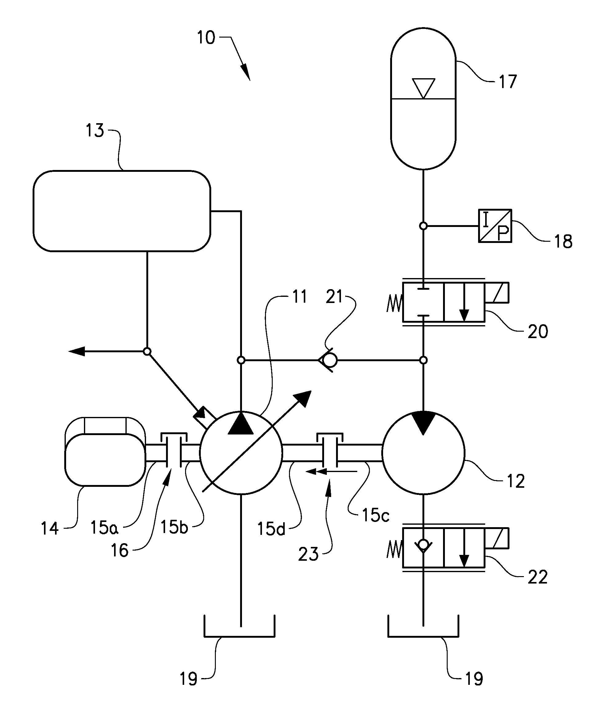
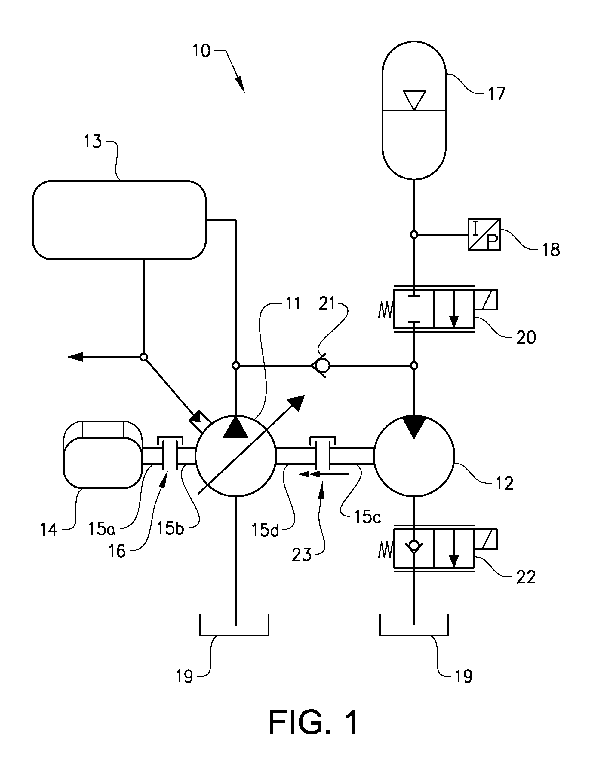
[0028]FIG. 1 shows a schematic illustration of a hydraulic system according to the invention. The figure shows a hydraulic system 10 comprising a controllable pump unit in the form of a variable displacement pump 11 for supplying hydraulic pressure to a hydraulically driven implement (not shown), which implement is controlled by an operator by means of schematically indicated proportional valves 13. The controllable variable displacement pump unit will hereafter be referred to as the pump 11. A prime mover in the form of an internal combustion engine 14 is arranged to supply a driving torque to the pump 11. Torque is transmitted by an output shaft 15a from the engine 14 via a transmission 16 in the form of a hydrodynamic gearbox to a drive shaft 15b for the pump 11. The transmission 16 can comprise a controllable clutch. The hydraulic system 10 further comprises a controllable motor unit in the form of a fixed displacement motor 12 connected to a hydraulic accumulator 17. The contro...

second embodiment

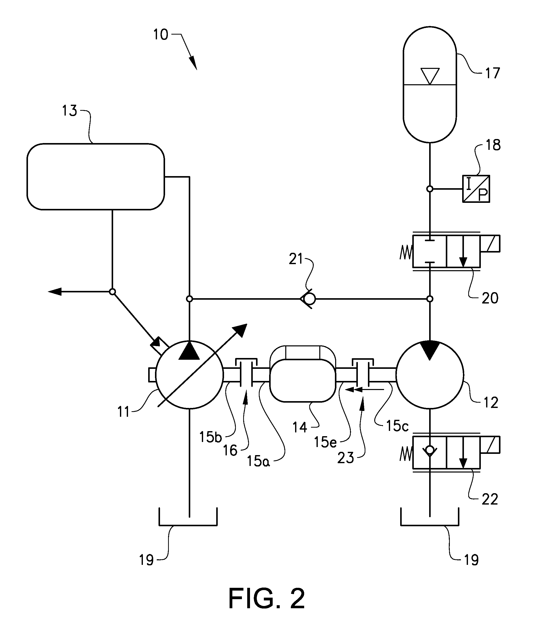
[0037]FIG. 2 shows a schematic illustration of a hydraulic system according to the invention. As in FIG. 1, FIG. 2 shows a hydraulic system 10 comprising a controllable pump unit in the form of a variable displacement pump 11 for supplying hydraulic pressure to a hydraulically driven implement (not shown), which implement is controlled by an operator by means of schematically indicated proportional valves 13. The controllable variable displacement pump unit will hereafter be referred to as the pump 11. A prime mover in the form of an internal combustion engine 14 is arranged to supply a driving torque to the pump 11. Torque is transmitted by an output shaft 15a from the engine 14 via a transmission 16 in the form of a hydrodynamic gearbox to a drive shaft 15b for the pump 11. The transmission 16 comprises a controllable clutch. The hydraulic system 10 further comprises a controllable motor unit in the form of a fixed displacement motor 12 connected to a hydraulic accumulator 17. The...


PUM


Abstract

A start / stop arrangement in a fluid system comprising a controllable pump unit for supplying fluid pressure to at least one implement; a prime mover connected to a transmission device arranged to drive the pump unit; wherein the pump unit is installed on an outgoing power take off and is arranged to supply fluid pressure to the implement fluid system, that the pump unit is arranged accumulate fluid pressure in the accumulator. The fluid system further comprises a controllable motor unit connected to a fluid accumulator; that fluid pressure from the accumulator is arranged to drive the motor unit; and that the motor unit is connected to the prime mover by an overrun clutch, wherein the motor unit is arranged to supply torque to and start the prime mover when at least one predetermined condition is fulfilled. The invention further relates to a method for controlling the start / stop arrangement.

Description

TECHNICAL FIELD[0001]The invention relates to a fluid system comprising a pump unit for supplying fluid pressure to at least one implement, where a prime mover arranged to supply a driving torque to the pump unit. The pump unit can be driven to accumulate fluid pressure in an accumulator which is used for driving a motor unit to start the prime mover or assist the prime mover during periods of high demand.BACKGROUND ART[0002]Fluid systems for wheel loaders, forklift trucks, container handling machines and other machines or vehicles are equipped with a prime mover for driving a fluid pump for instance via a gearbox. In such a system, a prime mover in the form of an internal combustion engine is usually operated continuously to drive the fluid pump.[0003]The prime mover is often connected to the pump or motor via a gearbox or a similar transmission arrangement, in order to achieve a desired rotational speed for driving a pump. The transmission and the prime mover have to be sized for ...

Claims


Application Information

Patent Timeline
Patent Type & Authority Applications(United States)
IPC IPC(8): F15B1/02
CPCB66F9/22F15B2211/851E02F9/2246E02F9/2292E02F9/2296F02D41/021F02N7/08F15B1/024F15B21/14F15B2211/20523F15B2211/20546F15B2211/88F15B1/02F15B2211/212F15B2211/6306F15B2211/6313F15B2211/633F15B2211/7058E02F9/2217F02N7/00F02N11/0814F02N15/02
Inventor ROSTH, MARCUS
Owner PARKER HANNIFIN AB
Why Eureka
Try Eureka