Near field communications reader

a reader and near field technology, applied in the field of near field communication (nfc) readers, to achieve the effect of low antenna input impedan

Active Publication Date: 2013-05-09
QUALCOMM TECH INT
View PDF10 Cites 21 Cited by
  • Summary
  • Abstract
  • Description
  • Claims
  • Application Information

AI Technical Summary

Benefits of technology

[0019]The near field communications reader may further comprise an impedance transformer for matching the input impedance of the antenna to the output impedance of the amplifier. This helps to maintain a low antenna input impedance.

Problems solved by technology

This gives rise to two problems.

Method used


Image

  • Near field communications reader
  • Near field communications reader
  • Near field communications reader

Examples


Embodiment Construction

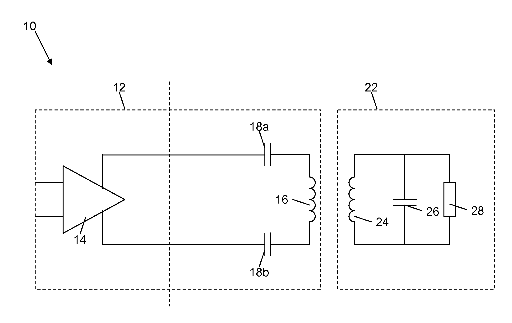
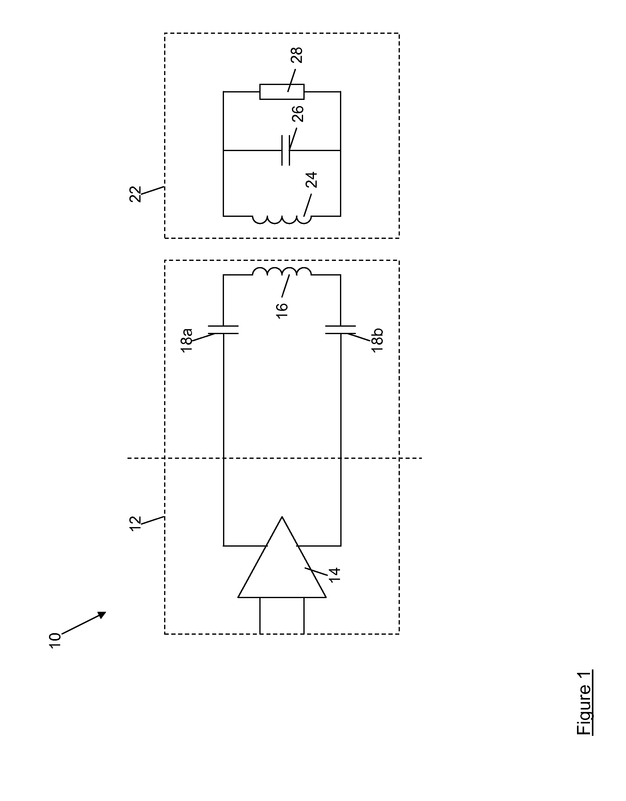
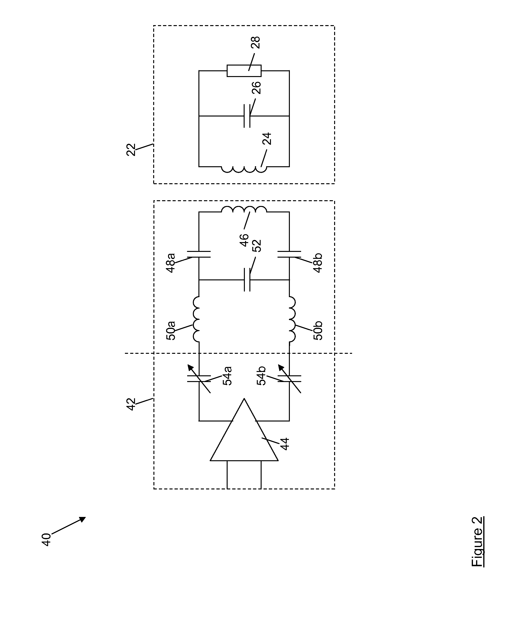
[0025]Referring now to FIG. 2, an NFC system is shown generally at 40, and comprises an NFC reader 42 which communicates with a tag 22. The tag 22 is identical in structure and function to the tag 22 illustrated in FIG. 1, and thus will not be described again here.

[0026]The NFC reader 42 comprises a power amplifier 44 whose output is connected to input terminals of an antenna 46 by means of an antenna filter. The antenna filter includes capacitors 48a, 48b, which are connected in series between differential outputs of the power amplifier 44 and the input terminals of the antenna 46. Thus, the capacitors 48a, 48b of the antenna filter and the inductance of the antenna 44 form a series resonant circuit.

[0027]The NFC reader 42 also includes inductors 50a, 50b which are connected in series between the differential outputs of the power amplifier 44 and the capacitors 48a, 48b, and a further capacitor 52 which is connected in parallel with the antenna 46. The capacitors 48a, 48b, 52 and t...


PUM


Abstract

The present application relates to a near field communications (NFC) reader which includes an amplifier that drives an antenna. Capacitors of fixed value are connected in series between differential outputs of the amplifier and inputs of the antenna and form a series resonant circuit with the impedance of the antenna. Variable capacitances are provided in series with the fixed value capacitors, and the capacitance of these variable capacitances can be adjusted to compensate for manufacturing tolerances in the fixed value capacitors which cause a frequency offset between a desired resonant frequency of the series resonant circuit its actual resonant frequency, and to compensate for changes in the input impedance of the antenna that occur as the distance between the antenna of the reader and an antenna of an NFC tag changes.

Description

CROSS-REFERENCE TO RELATED APPLICATIONS[0001]This application claims priority to United Kingdom Patent Application Number GB1119246.5 filed Nov. 8, 2011, entitled “A Near Field Communications Reader,” the entire disclosure of which is hereby incorporated by reference, for all purposes, as if fully set forth herein.TECHNICAL FIELD[0002]The present application relates to a near field communications (NFC) reader.BACKGROUND TO THE INVENTION[0003]Part of a typical known NFC system is shown schematically at 10 in FIG. 1. In the system of FIG. 1 an NFC reader 12 comprises a power amplifier 14 whose output is connected to input terminals of an antenna 16 by means of an amplifier filter having capacitors 18a, 18b which are connected in series between differential outputs of the power amplifier 16 and input terminals of the antenna 14.[0004]An NFC tag 22 communicates with the reader 12 by means of an antenna 24, with the other components of the tag 22 being represented by a capacitor 26 and a...

Claims


Application Information

Patent Timeline
Patent Type & Authority Applications(United States)
IPC IPC(8): G06K7/01H01Q5/10
CPCH01Q1/2225H04B5/0081H04B5/0031H03J3/20H03J7/12
Inventor MCFARTHING, ANTHONY L.
Owner QUALCOMM TECH INT
Why Eureka
Try Eureka