Impedance control circuit and semiconductor device including the same

a technology of impedance control circuit and semiconductor device, applied in logic circuits, pulse techniques, reliability increasing modifications, etc., can solve the problems of impedance mismatching, increased noise, and increased reflection of signals, and achieve the effect of reducing an impedance mismatch

Active Publication Date: 2013-05-09
SK HYNIX INC
View PDF2 Cites 26 Cited by
  • Summary
  • Abstract
  • Description
  • Claims
  • Application Information

AI Technical Summary

Benefits of technology

[0034]An embodiment of the present invention is directed to an impedance control circuit and a semiconductor device including the same capable of reducing an impedance mismatch between a pull-up termination unit and a pull-down termination unit that occurs due to parasitic resistance.

Problems solved by technology

However, as the swing width of the signals is reduced, an influence on the signals by external noises is increased and the reflection of the signals increase at interface ends of the semiconductor devices due to impedance mismatching (referred to as mismatch).
The impedance mismatching occurs due to a fluctuation in external noises or power supply voltages, a change in operation temperature, a change in manufacturing processes, or the like.
When the impedance mismatching occurs, it is difficult to transmit data at a high speed and distorted data may be output from a data output end of the semiconductor device.
Therefore, when the other semiconductor device receives the distorted output data as an input data at an input end, a setup / hold fail, a misjudgment of an input level, or the like, may be caused in the input data.
When using the plurality of termination units, various impedances may be set, but an error occurs between the targeted impedance value and the actual impedance value due to parasitic resistance occurring in a layout.
However, as the number of enabled pull-up termination units and the number of enabled pull-down termination units are increased, the error of the impedance value may be increased due to the parasitic resistance.

Method used


Image

  • Impedance control circuit and semiconductor device including the same
  • Impedance control circuit and semiconductor device including the same
  • Impedance control circuit and semiconductor device including the same

Examples


first embodiment

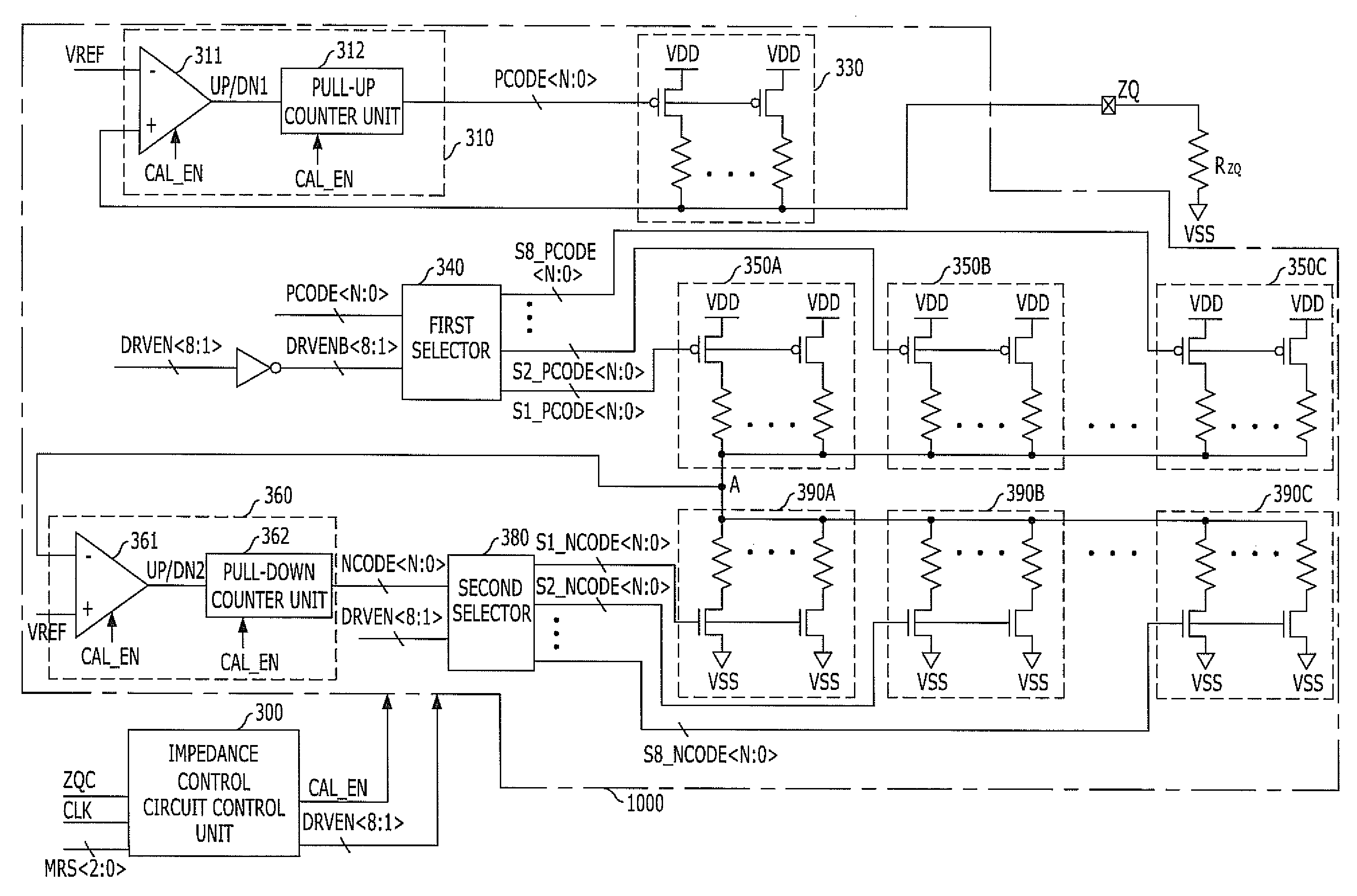
[0054]FIG. 4 is a diagram illustrating an impedance control circuit 1000 and an impedance control circuit control unit 300 in accordance with the present invention.

[0055]The impedance control circuit control unit 300 increases a value of a counting code CNT whenever a clock CLK is enabled and input from an instant that a calibration command ZQC is enabled and input and enables an calibration enable signal CAL_EN until the increased counting code CNT reaches a threshold value to be outputted to an impedance control circuit 1000. In this case, the threshold value is changed depending on a type of a calibration operation. For example, the threshold value may be 64 in the case of a short calibration mode and may be 256 or 512 in the case of a long calibration mode.

[0056]Meanwhile, the impedance control circuit control unit 300 decodes an output control signal MRS to generate M select signals DRVEN and outputs the generated M select signals to the impedance control circuit 1000. At least...

second embodiment

[0081]FIG. 6 is a diagram illustrating the impedance control circuit 1100 and the impedance control circuit control unit 300 in accordance with the present invention.

[0082]As illustrated in FIG. 6, the configuration and principle of the impedance control circuit control unit 300 are the same as the impedance control circuit control unit 300 illustrated in FIG. 4.

[0083]The impedance control circuit 1100 may include a pull-down code generator 410, a pull-down impedance unit 420, M dummy impedance units 470A, 4708, . . . , 470C, a pull-up code generator 430, and M pull-up impedance units 450A, 4508, . . . , 450C. The impedance control circuit 1100 illustrated in FIG. 6 is a different from the impedance control circuit 1000 illustrated in FIG. 4 in performing the pull-down calibration operation first and then, the pull-up calibration operation. Hereinafter, for description purposes, the case in which the impedance control circuit 1100 includes the 8 dummy impedance units 470A, 470B, . ....

third embodiment

[0101]FIG. 7A is a diagram illustrating the impedance control circuit 1200 and an impedance control circuit control unit 305 in accordance with the present invention.

[0102]The impedance control circuit control unit 305 generates the calibration enable signal CAL_EN, M select signals DRVEN, and M latch signals LATEN and outputs these signals to the impedance control circuit 1200. Hereinafter, for description purposes, the case in which the impedance control circuit control unit 305 generates the 8 select signals DRVEN and the 8 latch signals LATEN will be described by way of example.

[0103]More specifically, the impedance control circuit control unit 305 may include a clock counter unit 305A, a control logic unit 305B, a select signal generator 305C, and a latch signal generator 305D as illustrated in FIG. 7B.

[0104]The clock counter unit 305A counts the clock CLK to output a counting code CNT. More specifically, the clock counter unit 305A increases its own value of the counting code ...


PUM


Abstract

An impedance control circuit includes a pull-up code generator configured to generate pull-up impedance control codes using a voltage of a first node, a pull-up impedance unit configured to pull-up-drive the first node in response to the pull-up impedance control codes, a plurality of dummy impedance units enabled in response to respective select signals and each configured to pull-up-drive a second node in response to the pull-up impedance control codes, a pull-down code generator configured to generate pull-down impedance control codes using a voltage of the second node, and a plurality of pull-down impedance units enabled in response to the respective select signals and each configured to pull-down-drive the second node in response to the pull-down impedance control codes.

Description

CROSS-REFERENCE TO RELATED APPLICATIONS[0001]The present application claims priority of Korean Patent Application No. 10-2011-0116074, filed on Nov. 8, 2011, which is incorporated herein by reference in its entirety.BACKGROUND[0002]1. Field[0003]Exemplary embodiments of the present invention relate to an impedance control circuit generating an impedance control code for controlling an impedance value.[0004]2. Description of the Related Art[0005]Various types of semiconductor devices are integrated as integrated circuit chips such as CPUs, memories, gate arrays, and the like, in various electrical products such as a personal computer, a server, a workstation, and the like. In most cases, a semiconductor device includes a receiver circuit for receiving various signals transmitted from the outside through an input pad and an output circuit for transmitting signals from the semiconductor device to the outside through an output pad.[0006]Meanwhile, as an operation speed of electrical pro...

Claims


Application Information

Patent Timeline
Patent Type & Authority Applications(United States)
IPC IPC(8): H03K17/16
CPCH03K19/0005H03K19/018557H03K19/018585G11C7/10G11C7/22
Inventor KO, HYEONG-JUN
Owner SK HYNIX INC
Why Eureka
Try Eureka