Control unit and control method for reductant supply device

a technology of control unit and supply device, which is applied in the direction of engine components, mechanical equipment, machines/engines, etc., can solve the problems of electromagnetic control valves being likely to suffer heat damage, the supply system of liquid reductants will be partially or completely blocked, and the reductant injection valves will be partially or completely clogged, so as to prevent excessive cooling or heating of the reductant injection valve, stable atomization of the reductant, and effective cooling

Inactive Publication Date: 2013-05-16
BOSCH CORP
View PDF3 Cites 33 Cited by
  • Summary
  • Abstract
  • Description
  • Claims
  • Application Information

AI Technical Summary

Benefits of technology

[0037]According to the reductant supply device of the present invention, the reductant injection valve is cooled effectively by using the cooling water of the internal combustion engine. Further, while the temperature at the tip of the reductant injection valve is detected, the flow rate of the cooling water is adjusted in accordance with the detected temperature. As a result, it is possible to prevent excessive cooling or heating of the reductant injection valve. Accordingly, metal corrosion by ammonia and heat damage of the reductant injection valve is prevented, and crystallization of urea in the vicinity of the reductant injection valve is prevented. Thus, stable atomization of the reductant is realized.
[0038]Further, in the reductant supply device of the present invention, the controller controls the flow rate control valve such that the temperature at the tip of the reductant injection valve is between equal to or higher than 100° C. and equal to or lower than 120° C. Thus, metal corrosion by ammonia and heat damage of the reductant injection valve is prevented more stably, and crystallization of urea in the vicinity of the reductant injection valve is prevented more stably.
[0039]Further, in the reductant supply device of the present invention, the temperature sensor detects and calculates the temperature at the tip of the reductant injection valve. Therefore, it is possible to estimate the temperature at the tip of the reductant injection valve by using a known device structure, without using an additional temperature sensor.
[0040]Further, in the reductant supply device of the present invention, the cooling water of the internal combustion engine is used to adjust the temperature of the urea aqueous solution in the storage tank. Therefore, the urea aqueous solution having a temperature equal to or lower than the boiling point is inhibited from being injected without adjustment from the reductant injection valve. As a result, crystallization of urea in the vicinity of the nozzle hole is inhibited more reliably.
[0041]Moreover, according to the control method for the reductant supply device of the present invention, when the reductant injection valve is cooled by circulating the cooling water of the internal combustion engine, the circulation amount of the cooling water is adjusted based on the temperature of the reductant injection valve. Thus, metal corrosion by ammonia and heat damage of the reductant injection valve is prevented, and crystallization of urea due to excessive cooling of the reductant injection valve is prevented. Accordingly, stable atomization of the reductant is realized.

Problems solved by technology

In this type of exhaust gas purification device, if a urea aqueous solution is used as a liquid reductant and the temperature of the urea aqueous solution becomes excessively high, urea is hydrolyzed and crystallized before the urea aqueous solution is injected from the reductant injection valve.
As a result, there is a possibility that a supply system of the liquid reductant will be partially or completely clogged.
As a result, the electromagnetically controlled valve is likely to suffer from heat damage caused by heat being transferred from the exhaust pipe.

Method used


Image

  • Control unit and control method for reductant supply device
  • Control unit and control method for reductant supply device
  • Control unit and control method for reductant supply device

Examples


Embodiment Construction

[0047]Hereinafter, an embodiment relating to a reductant supply device and a control method for the reductant supply device of the present invention will be described concretely with reference to the appended drawings. However, the embodiment is just one form of the present invention and in no way limits the present invention, and any modification can be made within the scope of the present invention.

[0048]Note that, in the respective drawings, structural members that are the same are denoted with the same reference numerals, and explanation thereof is omitted as appropriate.

[0049]1. Exhaust Gas Purification Device

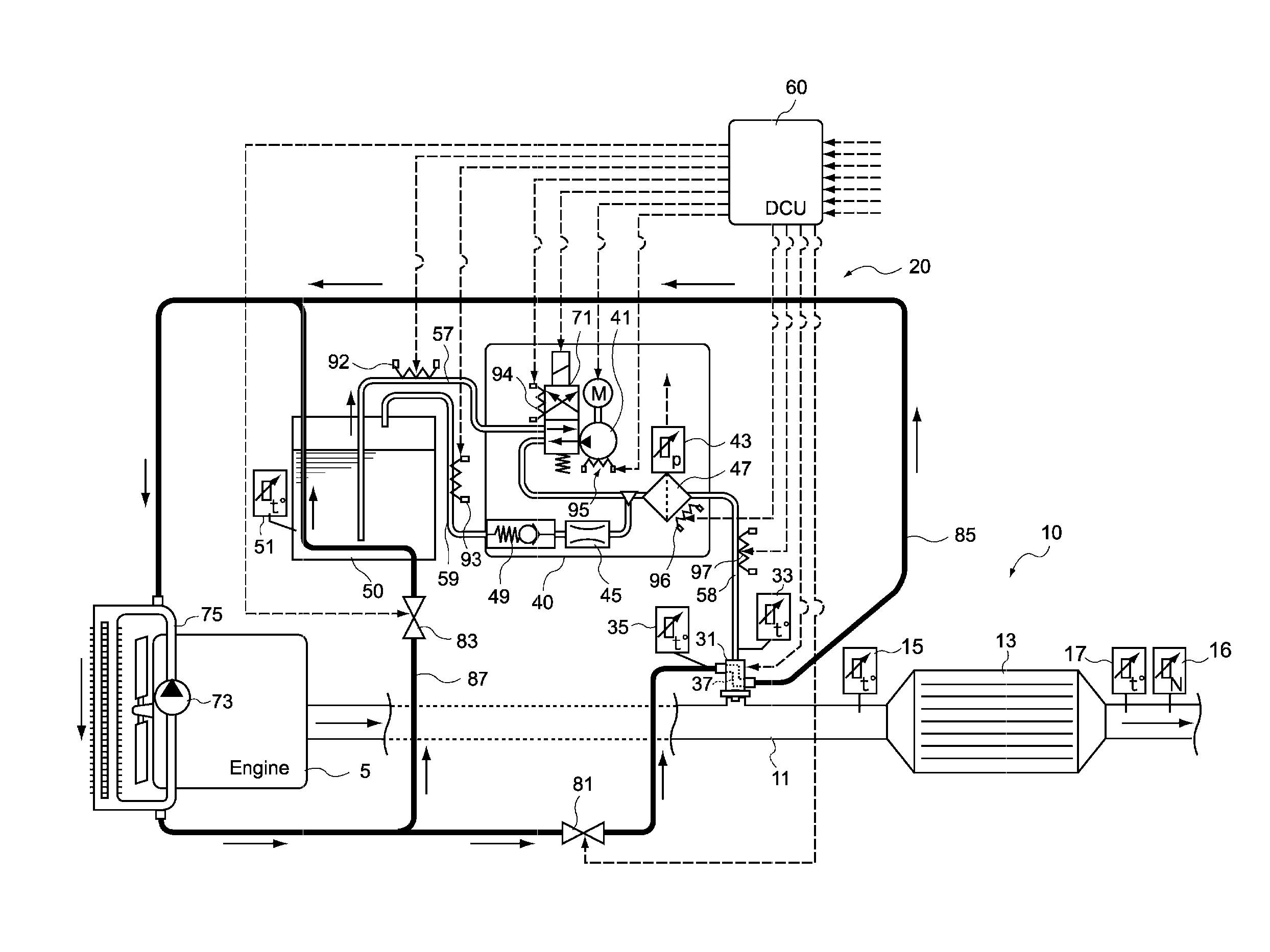
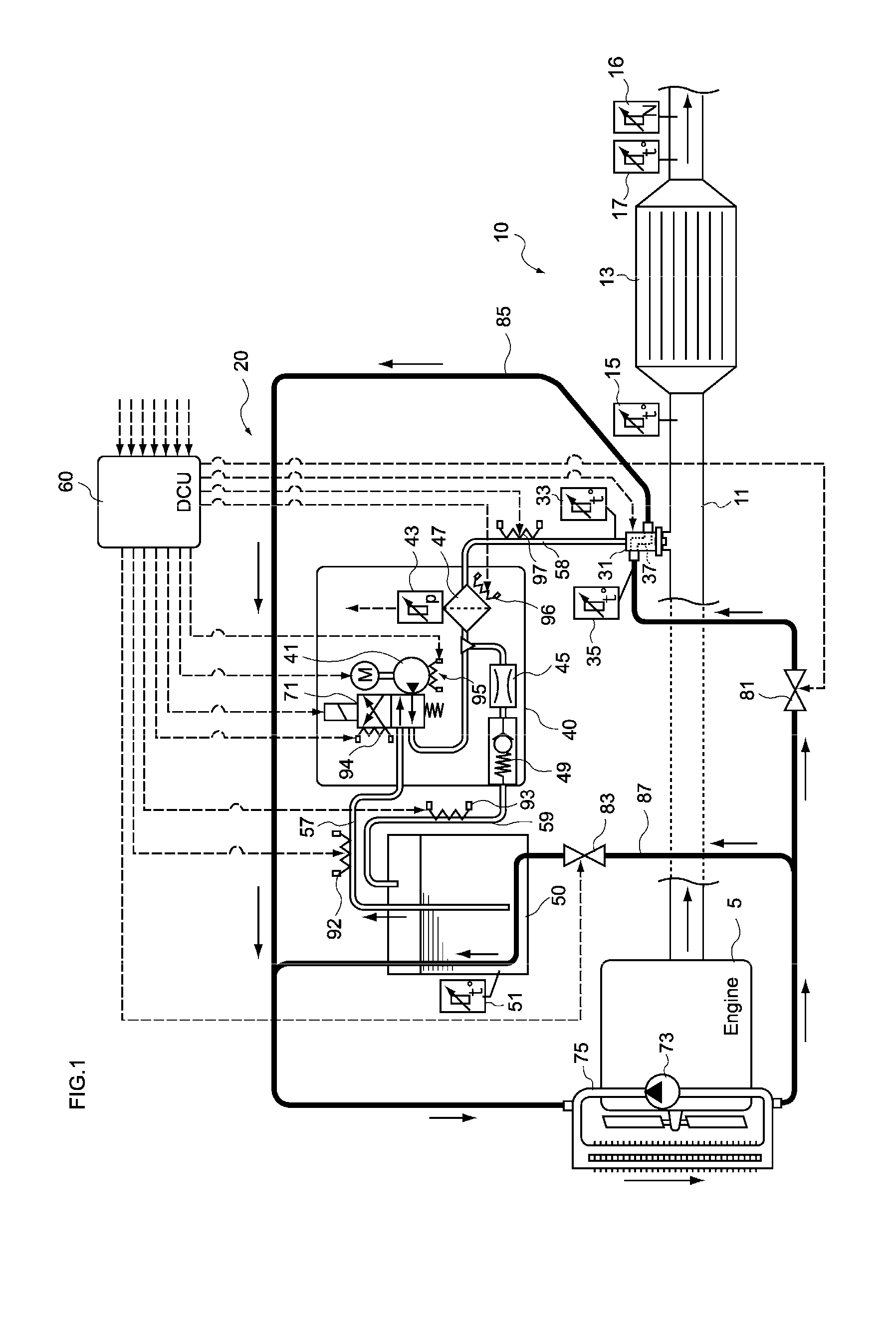
[0050]First, an example of the structure of an exhaust gas purification device in which a reductant supply device of the present embodiment is provided will be described with reference to FIG. 1.

[0051]An exhaust gas purification device 10 shown in FIG. 1 directly injects and supplies a urea aqueous solution serving as a liquid reductant which is pressure-fed to the reducta...


PUM


Abstract

A reductant supply device having a reductant injection valve with an injection tip that is fixed to an exhaust pipe on the exhaust gas upstream side of a reduction catalyst, the device directly injecting and supplying an urea aqueous solution which is pressure-fed to the reductant injection valve in a state of a liquid fluid, by controlling opening and closing of the reductant injection valve. The device includes a cooling water circulation passage; a flow rate control valve; a temperature sensor for detecting a temperature at the tip of the reductant injection valve; and a controller for controlling the flow rate control valve based on the temperature at the tip such that the temperature at the tip of the reductant injection valve is maintained at a temperature between equal to or higher than a boiling point of the urea aqueous solution and equal to or lower than 130° C.

Description

PRIORITY[0001]This application is a continuation in part of U.S. patent application Ser. No. 12,738,414 entitled “Control Unit and Control Method for Reductant Supply Device”, and filed on Apr. 16, 2010. The aforementioned application is incorporated herein by reference for all purposes.TECHNICAL FIELD[0002]The present invention relates to a reductant supply device and a control method used in an exhaust gas purification device. Particularly, the present invention relates to a reductant supply device that uses a urea aqueous solution as a reductant and that cools a reductant injection valve by circulating cooling water for cooling an internal combustion engine, and a control method for the reductant supply device.BACKGROUND OF THE INVENTION[0003]Generally, exhaust gas discharged from an internal combustion engine, such as a diesel engine, contains nitrogen oxides (hereinafter referred to as NOX) that may have an impact on the environment. As an exhaust gas purification device used t...

Claims


Application Information

Patent Timeline
Patent Type & Authority Applications(United States)
IPC IPC(8): F01N3/10
CPCF01N3/10F01N3/208F01N2610/11F01P2060/16Y02T10/24F01P3/20F01N2900/1811Y02T10/12
Inventor DOMON, WATARUIGARASHI, HIROYUKINAKAO, EIJI
Owner BOSCH CORP
Why Eureka
Try Eureka