

On-vehicle motor including detector for detecting state of motor
a technology for detecting state and motors, applied in the field of motors, can solve problems such as difficulty in shrinking the size of the motor in the axial direction, and achieve the effects of reducing the electrical noise entering from the axial direction of the detector and enhancing the controllability of the motor
- Summary
- Abstract
- Description
- Claims
- Application Information
AI Technical Summary
Benefits of technology
Problems solved by technology
Method used
Image

Examples
first embodiment
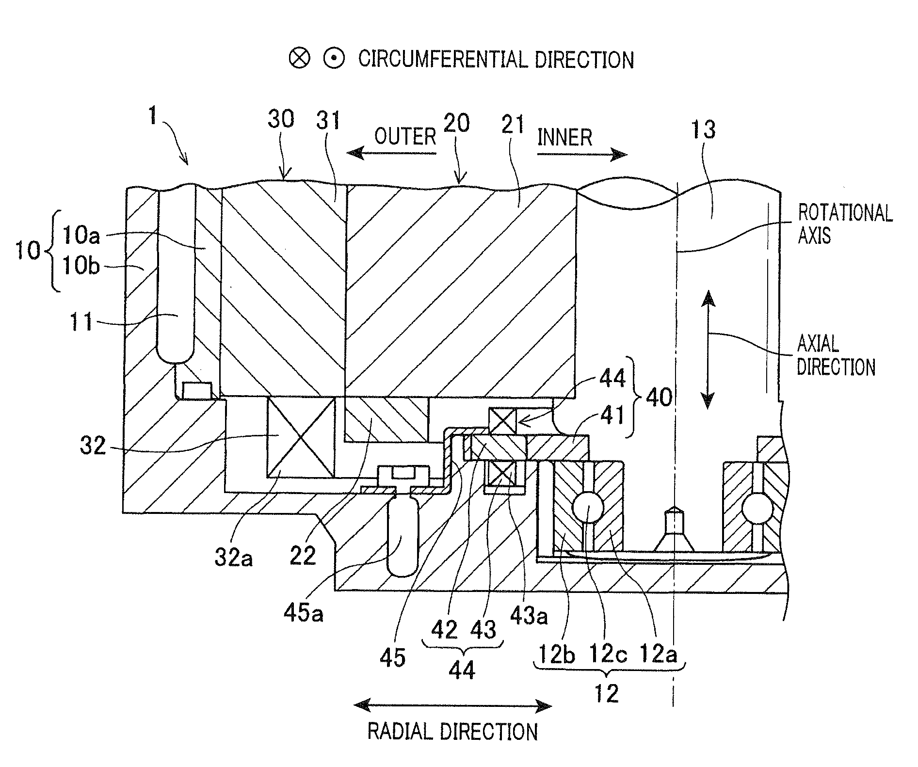
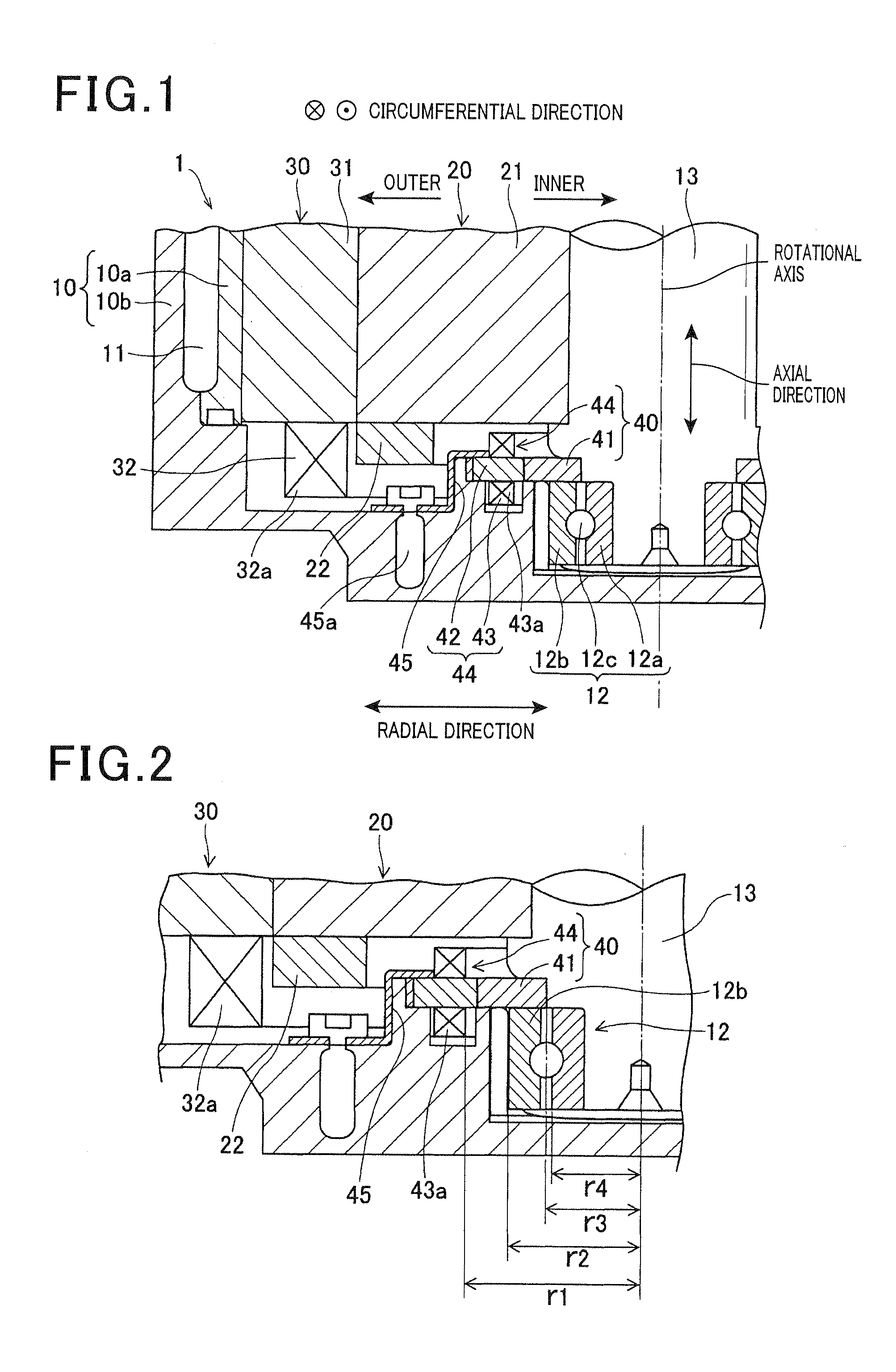
[0026]FIG. 1 is a cross-sectional view in the axial direction of a motor according to the first embodiment showing an enlarged major portion of the motor. FIG. 2 is a cross-sectional view in the axial direction showing the major portion being further enlarged from that of FIG. 1.
[0027]The motor 1 according to the first embodiment is an induction motor mounted on a vehicle. As shown in FIG. 1, the motor 1 includes a housing 10 made of aluminum, a shaft 13, a rotor 20, a stator 30 and a resolver 40. The rotor 20 is capable of rotating about a rotational axis in the shaft 13 being extended in the axial direction (i.e., longitudinal direction of the shaft 13). The shaft 13, the rotor 20 and the stator 30 are disposed to be adjacent in the radial direction. The resolver 40 serves as a detector that detects the rotational speed of the rotor 20.
[0028]Specifically, the shaft 13 is supported by the housing 10 such that both ends (i.e., first and second ends) of the shaft 13 in the axial dire...
second embodiment
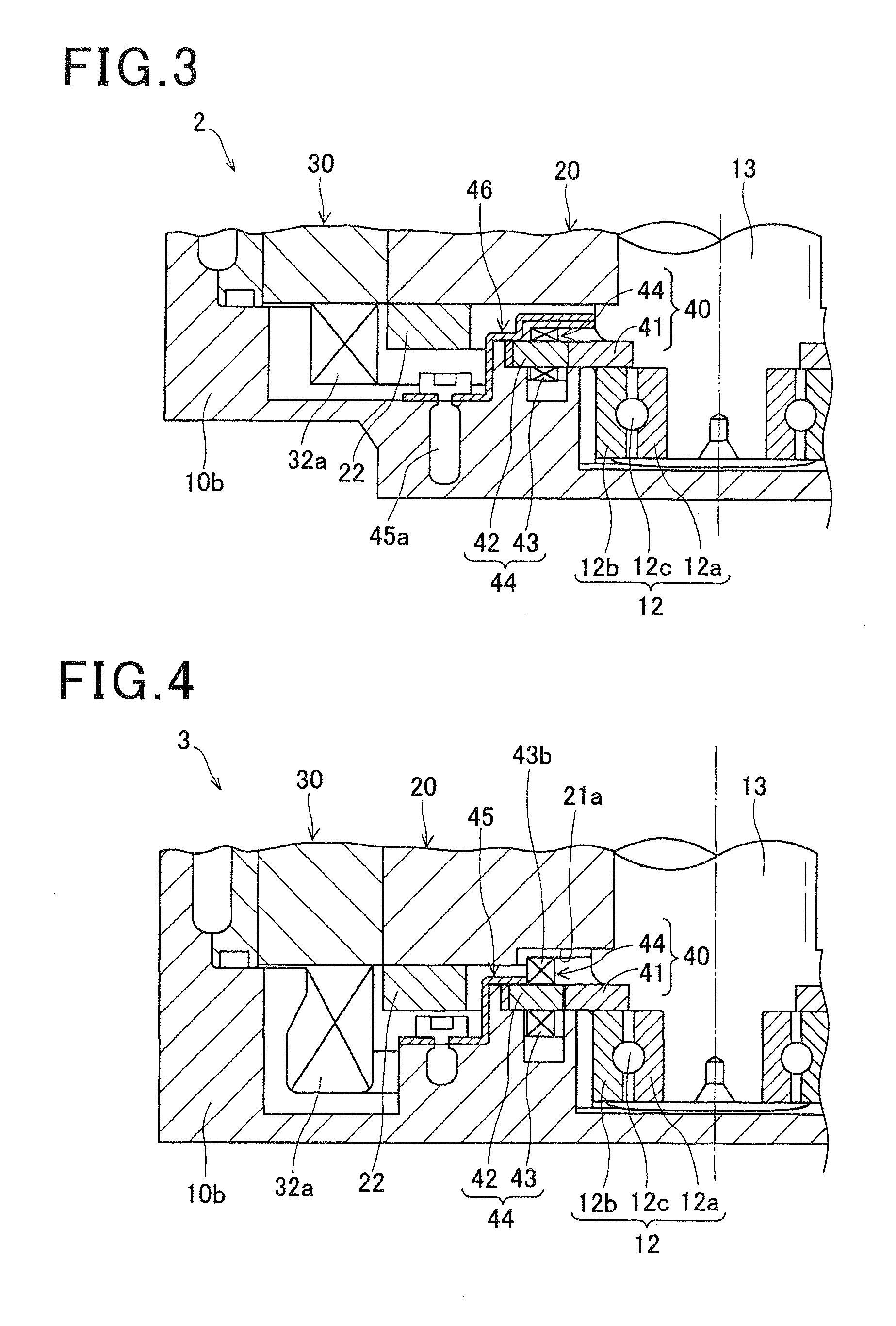
[0044]FIG. 3 is a cross-sectional view in the axial direction of the motor according to the second embodiment, showing an enlarged major portion of the motor. The motor 2 according to the second embodiment is an induction motor of which overall configuration is similar to that of the first embodiment, however, only a configuration of the retainer plate 46 differs from the first embodiment. Therefore, in the second embodiment, components identical with or similar to those in the first embodiment are given the same reference numerals and the explanation thereof is omitted. Hereinafter, configurations differing from the first embodiment are described.
[0045]As similar to the first embodiment, the retainer plate 46 according to the second embodiment is made of iron type metal (magnetic body) and fixed to the inner wall surface of the rear housing 10b. However, a configuration in which the retainer plate 46 is disposed to cover the outer circumferential side of the resolver 40 and an end ...
third embodiment
[0047]FIG. 4 is a cross-sectional view in the axial direction of a motor according to the third embodiment, showing an enlarged major portion of the motor. The motor 3 according to the third embodiment is an induction motor of which overall configuration is similar to that of the first embodiment. Also, the resolver 40 is similar to that of the first embodiment, however, the resolver 40 is arranged differently from that of the first embodiment. Accordingly, in the third embodiment, the components identical with or similar to those in the first embodiment are given the same reference numerals and the explanation thereof is omitted. Hereinafter, configurations differing from the first embodiment are described.
[0048]In the third embodiment, a concave portion 21a is disposed at the inner circumferential side of one end surface in the axial direction of the rotor core 21. The concave portion 21a is extended to the circumferential direction with a predetermined depth and width so as to fo...
PUM
 Abstract
Description
Claims
Application Information