Switching amplifier with pulsed current supply

a technology of pulsed current supply and switching amplifier, which is applied in the direction of amplifiers with semiconductor devices/discharge tubes, power conversion systems, dc-dc conversion, etc., can solve the problems of inefficient power usage, excessive losses, and short dead times, and achieve high efficiency.

Inactive Publication Date: 2013-05-16
HSIEH WEN HSIUNG
View PDF24 Cites 6 Cited by
  • Summary
  • Abstract
  • Description
  • Claims
  • Application Information

AI Technical Summary

Benefits of technology

[0016]From the switching amplifier in accordance with the present invention, one aspect of the present invention provides a switching amplifier that is highly efficient and without the “dead time” problem related to the class D amplifiers.

Problems solved by technology

In general, class A amplifiers produce a linearly amplified replica of an input signal, but are inefficient in terms of power usage because the amplifying elements are always biased and conducting, even if there is no input.
This arrangement gives excellent efficiency, but can suffer from the drawback that there is a small mismatch in the cross-over region—at the “joins” between the two halves of the signal, as one output device has to take over supplying power exactly as the other finishes.
However, one significant challenge for a driver circuit in class D amplifiers is keeping dead times as short as possible.
Dead times need to be as short as possible to maintain an accurate low-distortion output signal, but dead times that are too short cause the MOSFET that is switching on to start conducting before the MOSFET that is switching off has stopped conducting.
Driver failures that allow shoot-through result in excessive losses and sometimes catastrophic failure of the MOSFETs.
Therefore, the main disadvantage of a class D amplifier is having the “dead time” problem to cause the distortion of the output signal.
In summary, class A amplifiers produce a linearly amplified replica of an input signal, but are inefficient in terms of power usage.
The push-pull class B amplifiers provide excellent efficiency (compared to class A amplifiers), but introduce crossover distortion.
Class D amplifiers are most efficient compared to class A and class B amplifiers, but there is one significant problem for MOSFET driver circuits in class D amplifiers: the “dead time” that cause the distortion of the output signal.

Method used


Image

  • Switching amplifier with pulsed current supply
  • Switching amplifier with pulsed current supply
  • Switching amplifier with pulsed current supply

Examples


first embodiment

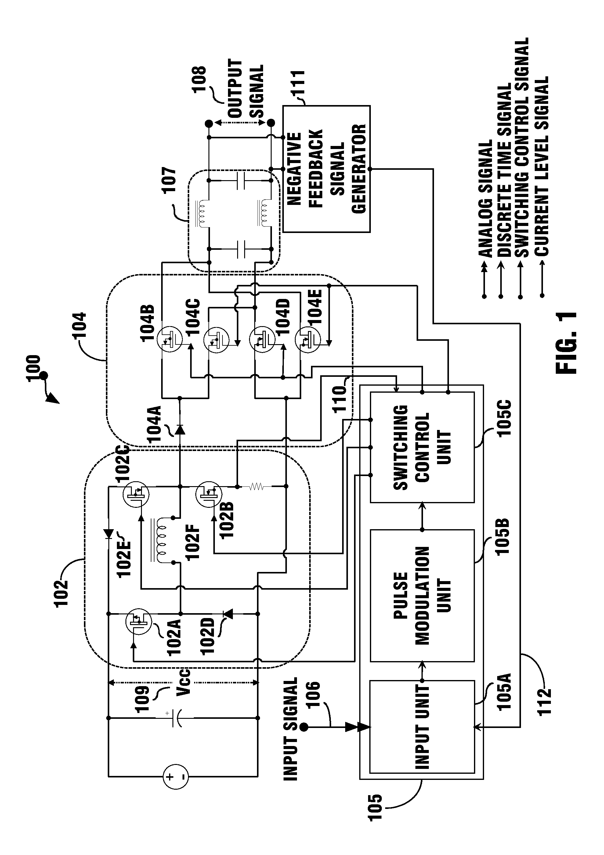
[0027]FIG. 1 is an exemplary block and circuit diagram illustrating a switching amplifier 100 in accordance with present invention, wherein the pulsed current supply unit 102 using an inductor 102F.

[0028]As illustrated in FIG. 1, the switching amplifier 100 of the present invention for amplifying an input signal 106 having positive and negative polarities is comprised of: a pulsed current supply unit 102 having a plurality of switches for switching a pulsed direct current (DC) current from a direct current (DC) voltage 109; a switching power transmitting unit 104 having a plurality of switches and coupled to the pulsed current supply unit 102 for conducting the pulsed direct current (DC) current positively or negatively; an amplifier control unit 105 for receiving the input signal 106 and coupled to the switches of the pulsed current supply unit 102 and the switching power transmitting unit 104 to control their switching according to the input signal 106; a filter unit 107 to obtain...

exemplary embodiment 100

[0034]In this non-limiting exemplary embodiment 100, the amplifier control unit 105 is a digital signal processing circuit. And it is obvious for a corresponding embodiment of an analog signal processing circuit for the amplifier control unit 105 in accordance with this invention by using an input unit for receiving an analog input signal and a pulse modulator for pulse modulating said analog input signal.

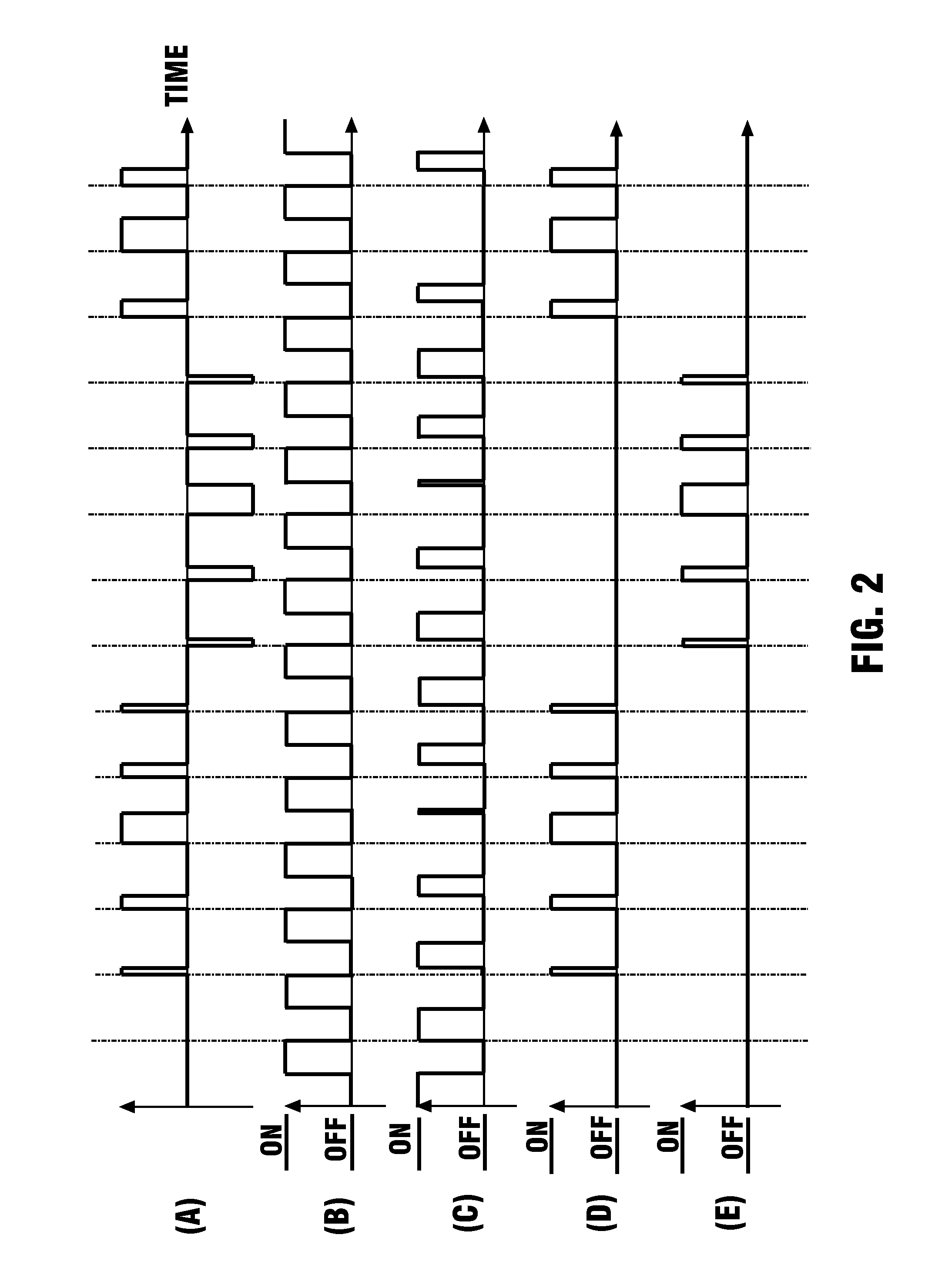
[0035]FIG. 2 are exemplary waveform diagrams illustrating the various waveforms at input and output points of switching control units in the circuits of various figures in accordance with the present invention.

[0036]As illustrated in FIG. 2, a non-limiting exemplary waveform for the pulse modulated signal from the pulse modulation unit 105B is illustrated in FIG. 2(A), since the input signal 106 has first and second polarities; therefore, the pulse modulated signal also has first and second polarities. According to the pulse modulated signal illustrated in FIG. 2(A), a non-limiting...

second embodiment

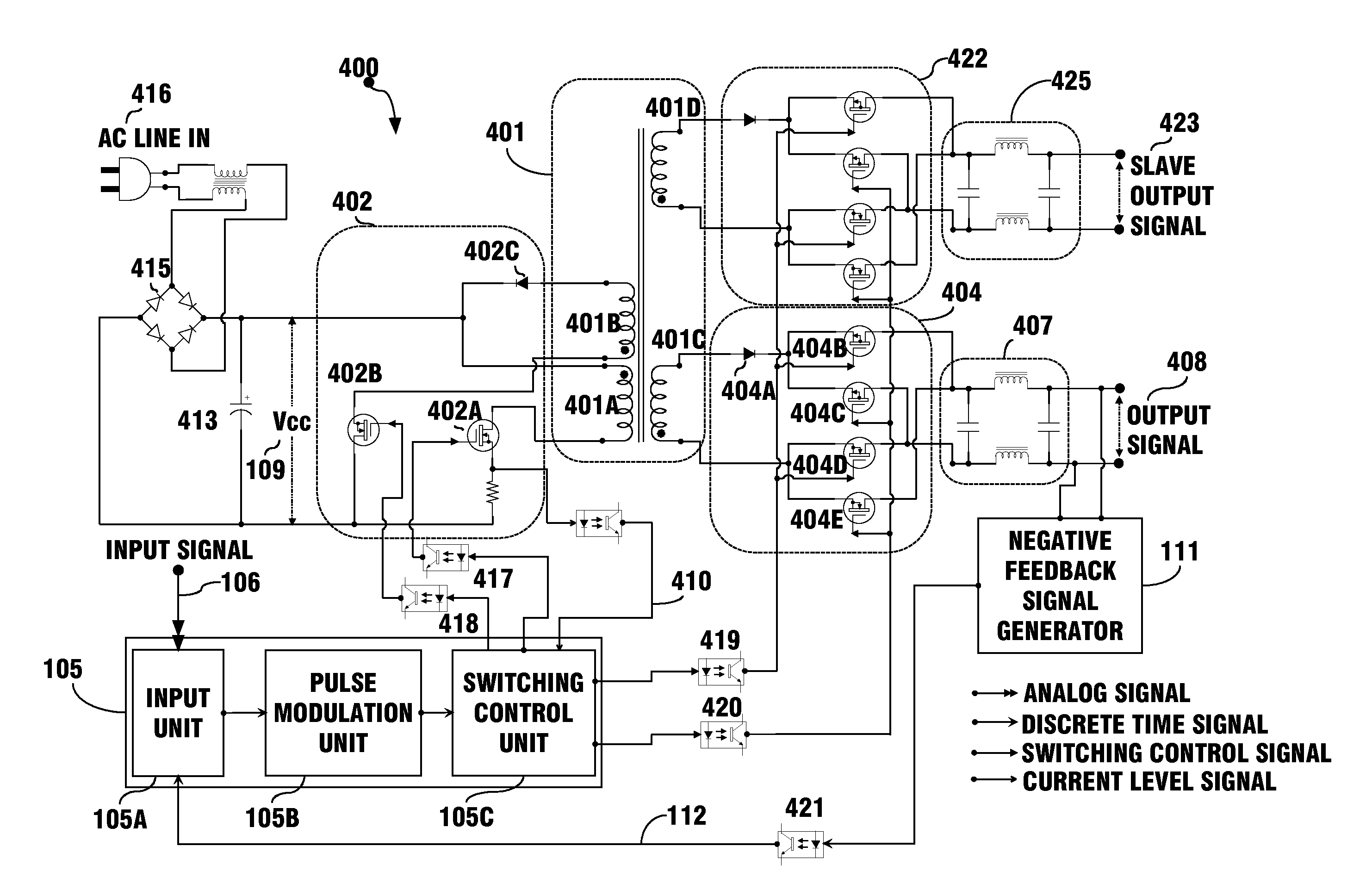
[0048]FIG. 4 is an exemplary block and circuit diagram illustrating a switching amplifier 400 in accordance with present invention.

[0049]As illustrated in FIG. 4, the switching amplifier 400 of the present invention for amplifying an input signal 106 having positive and negative polarities is comprised of: a pulsed current supply unit having a plurality of switches 402 for switching a pulsed direct current (DC) current from a direct current (DC) voltage 109; a switching power transmitting unit 404 having a plurality of switches 404B, 404C, 404D, 404E and coupled to the pulsed current supply unit for conducting the pulsed direct current (DC) current positively or negatively; an amplifier control unit 105 for receiving the input signal 106 and coupled to the switches 402 of the pulsed current supply unit and the switching power transmitting unit 404 to control their switching according to the input signal 106; a filter unit 407 to obtain an output signal 408 corresponding to the input...


PUM


Abstract

A switching amplifying method or a switching amplifier for obtaining one or more than one linearly amplified replicas of an input signal, is highly efficient, and does not have the disadvantage of “dead time” problem related to the class D amplifiers. Said switching amplifying method comprises the steps of: receiving the input signal; pulse modulating the input signal for generating a pulse modulated signal; switching a pulsed current from a direct current (DC) voltage according to the pulse modulated signal; conducting said pulsed current positively or negatively to a filter according to the polarity of the input signal; filtering said pulsed current positively or negatively conducted to the filter for outputting an output signal by the filter.

Description

BACKGROUND OF THE INVENTION[0001](1) Field of the Invention[0002]This invention is related in general to a power amplifier, and more particularly, to a switching amplifier that can efficiently and linearly amplify an input signal having first and second polarities for obtaining a low-distortion output signal.[0003](2) Description of the Related Art[0004]Amplifiers are electronic devices which are used for increasing the power of a signal, and are generally categorized into various classes. The popular amplifiers include class A, class B and class D amplifiers. Reference is made to the exemplary U.S. Patents that disclose various types of amplifiers: U.S. Pat. Nos. 7,952,426; 7,816,985; 7,400,191; 7,286,008; 6,922,101; 6,794,932; 6,563,377; 6,356,151; 6,282,747; 5,949,282; 5,805,020; 5,767,740; 5,160,896; 5,115,205; 5,014,016; 4,531,096 and 3,629,616.[0005]In general, class A amplifiers produce a linearly amplified replica of an input signal, but are inefficient in terms of power usa...

Claims


Application Information

Patent Timeline
Patent Type & Authority Applications(United States)
IPC IPC(8): H02M3/335H03F3/217
CPCH03F3/217H03F3/38
Inventor HSIEH, WEN-HSIUNG
Owner HSIEH WEN HSIUNG
Why Eureka
Try Eureka