Infrared laser

a laser and infrared technology, applied in the field of infrared lasers, can solve the problems of difficult implementation of passive mode-locked or q-switched infrared lasers

Active Publication Date: 2013-05-16
NAVY U S A AS REPRESENTED BY THE SEC OF THE THE
View PDF2 Cites 16 Cited by
  • Summary
  • Abstract
  • Description
  • Claims
  • Application Information

AI Technical Summary

Benefits of technology

[0015]In various implementations, linear and/or ring cavities can be employed with more than two mirrors, for instance, to fold the cavity. Also, oth

Problems solved by technology

Thusfar, implementing passive mode-locked or Q-switched infrared lasers has been difficult, especially at infrared wavelengths,

Method used


Image

  • Infrared laser
  • Infrared laser
  • Infrared laser

Examples


Embodiment Construction

[0036]One or more embodiments or implementations are set forth in conjunction with the drawings, where like reference numerals refer to like elements throughout, and where the various features are not necessarily drawn to scale.

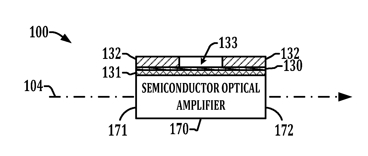
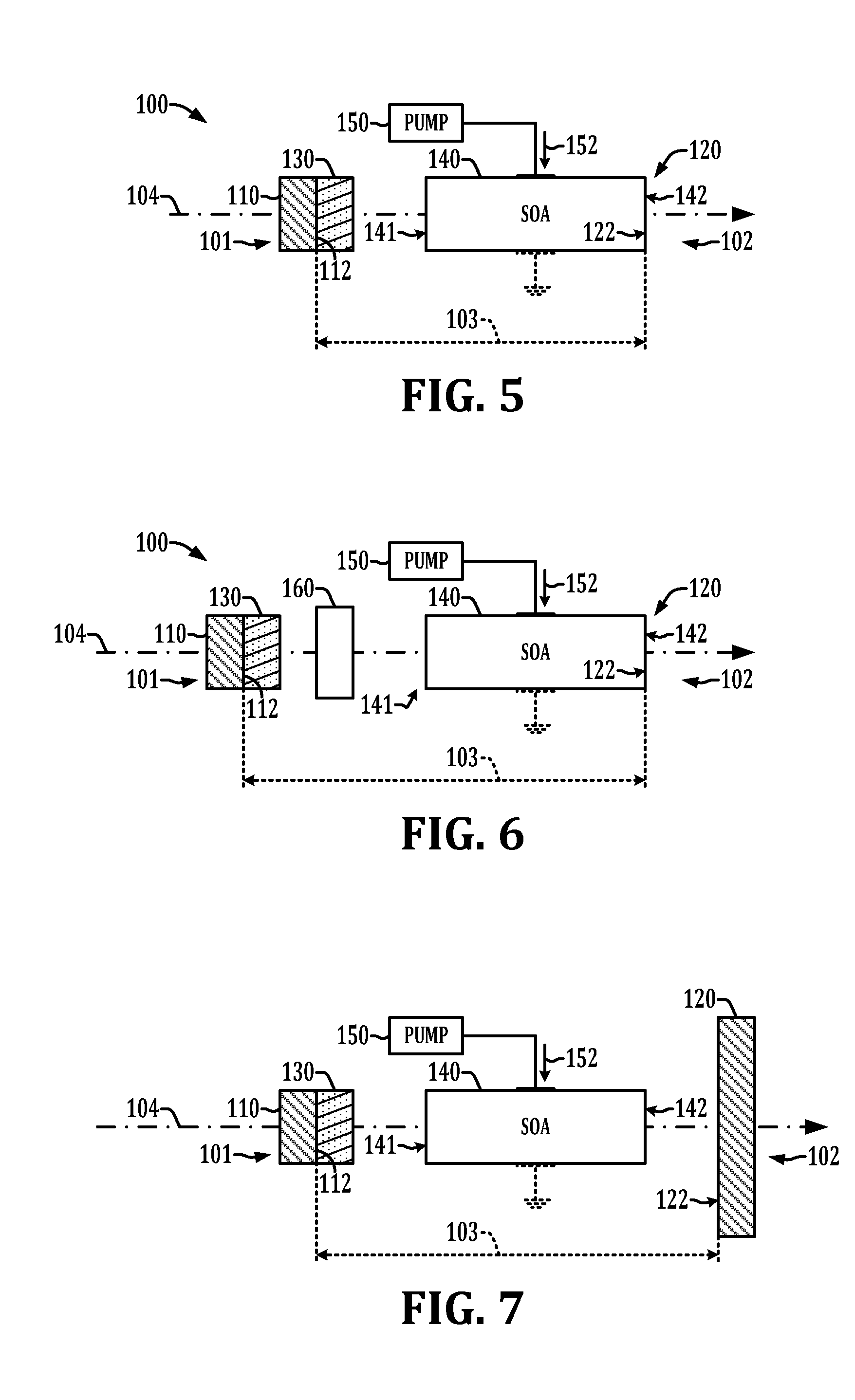
[0037]Semiconductor optical amplifiers for ultraviolet, visible, and near infrared wavelengths typically have an interband design in which photons are emitted by the recombination of electron-hole pairs across the material bandgap. Semiconductor optical amplifiers for infrared wavelength can have interband cascade semiconductor optical amplifier design or quantum cascade semiconductor amplifier design. The interband cascade semiconductor optical amplifier laser typically operate in the wavelength range of 3-5 μm and quantum cascade semiconductor optical amplifier typically operate in the wavelength range of in the 5-18 μm but terahertz lasers to 200 micron wavelength have been experimentally demonstrated. The semiconductor optical amplifier designs typically ...


PUM


Abstract

Laser devices are presented in which a graphene saturable absorber and an optical amplifier are disposed in a resonant optical cavity with an optical or electrical pump providing energy to the optical amplifier.

Description

REFERENCE TO RELATED APPLICATION[0001]This application claims priority to and the benefit of U.S. Provisional Patent Application Serial No. 61 / 559,308, filed Nov. 14, 2011, and entitled “Method for Implementing Infrared Laser”, the entirety of which is hereby incorporated by reference.BACKGROUND[0002]Laser devices provide output from an optical cavity when an included gain medium overcomes the cavity losses so that amplification via stimulated emission occurs. Lasers produce light over some natural bandwidth or range of frequencies, sometimes referred to as the gain bandwidth, which is largely determined by the laser gain medium and the optical cavity or resonant cavity of the laser. Saturable absorbers can be introduced into the optical cavity to provide variability in the cavity loss, which is typically nonlinear such that when a small number of photons are present there is a larger cavity loss than when a large number of photons are present. This allows Q-switching to occur if th...

Claims


Application Information

Patent Timeline
IPC IPC(8): H01S3/10H01S3/091H01S3/09
CPCH01S3/10H01S5/10H01S3/091B82Y20/00H01S3/06H01S3/083H01S3/1118H01S3/113H01S5/028H01S5/0601H01S5/1032H01S5/14H01S5/1838H01S5/3401H01S5/50H01S3/1106H01S3/1112H01S3/11H01S3/0906H01S3/1115H01S3/081H01S3/0813H01S3/0815
Inventor KUB, FRANCIS J.CURRIE, MARC
Owner NAVY U S A AS REPRESENTED BY THE SEC OF THE THE
Why Eureka
Try Eureka