
Electrode lead connection body, nonaqueous electrolyte electricity storing device and method of manufacturing the same

a technology of electrolyte storage device and electrode lead, which is applied in the direction of cell components, final product manufacturing, sustainable manufacturing/processing, etc., can solve the problems of poor workability of a form of assembled battery after connection, difficulty in obtaining sufficient sealing properties, and poor workability of the resin after connection, so as to achieve high joint reliability and sufficient joint strength

Inactive Publication Date: 2013-05-16
HITACHI METALS LTD
View PDF3 Cites 13 Cited by
  • Summary
  • Abstract
  • Description
  • Claims
  • Application Information

AI Technical Summary

Benefits of technology

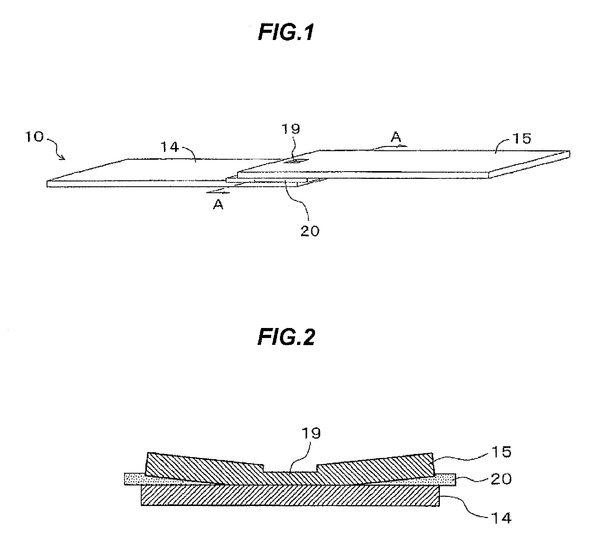
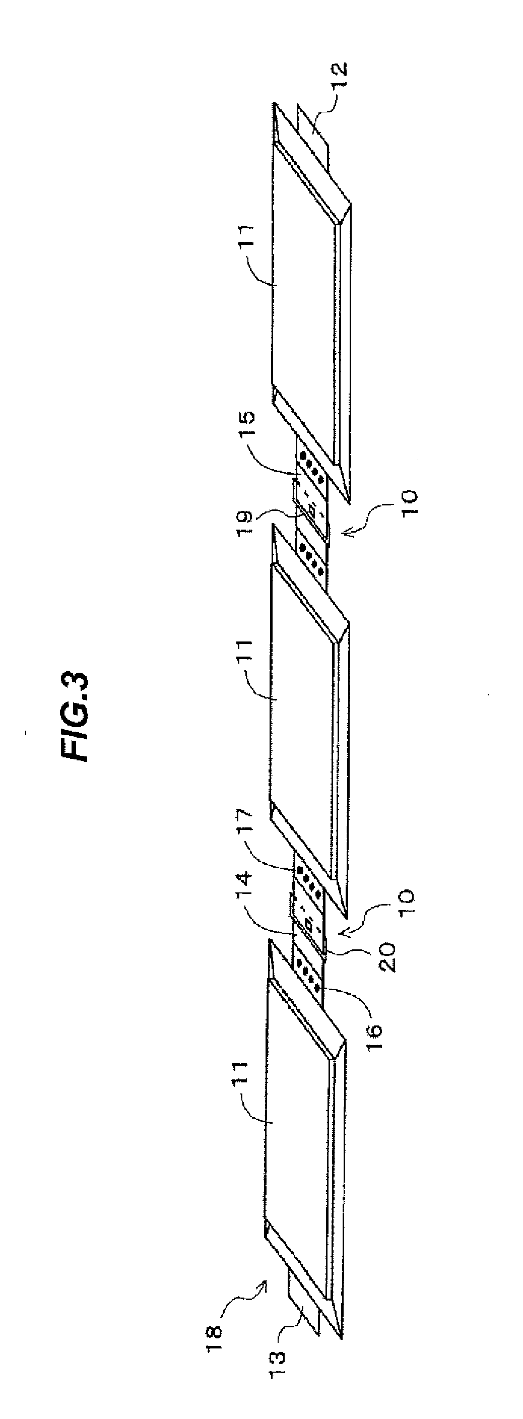
The invention provides an electrode lead connection body that can connect positive and negative electrode leads made of different metals with a high mechanical strength and long-term joint stability. This simplifies the assembly process of a nonaqueous electrolyte electricity storing device and ensures secure connection and downsizing. The connection body has a first and second member joined together with an insulating material in between to prevent corrosion caused by the local cell effect. The technical effects of the invention are improved reliability and stability of the electrode lead connection.

Problems solved by technology

With respect to JP-A-2008-108584, since the lead member overlaps with a sealed portion of the outer package at a corrosion-resistant material portion covering the joint portion between the first and second members of and is thus thicker than a lead member not being covered, it is considered difficult to obtain sufficient sealing properties in a process of thermally sealing the outer package and there is concern about leakage of electrolytic solution.
With respect to Japanese patent No. 3931983 and JP-A-2004-247244, although a resin-covered portion formed by covering a joint between dissimilar metals of the lead member is located outside of the outer package, there is concern that the resin-covered portion is damaged by contact with a manufacturing tool during the process of thermally sealing the outer package at the time of manufacturing a battery cell and design limitation is imposed such that a length of an electrode lead portion from an edge of the outer package to an edge of the resin-covered portion is increased to be larger than the size of the manufacturing tool, which arises problems in downsizing and thinning of a nonaqueous electrolyte electricity storing device.
In addition, when the electrode lead portion is joined to a dissimilar metal and is covered with a resin after manufacturing the battery cell, workability for covering the resin in a form of assembled battery after connection is poor and defective products causes great loss, which affects not only the lead member but also the battery cell or more.

Method used


Image

  • Electrode lead connection body, nonaqueous electrolyte electricity storing device and method of manufacturing the same
  • Electrode lead connection body, nonaqueous electrolyte electricity storing device and method of manufacturing the same
  • Electrode lead connection body, nonaqueous electrolyte electricity storing device and method of manufacturing the same

Examples


example 1

[0062]An Al plate having a thickness of 0.3 mm, a width of 30 mm and a length of 50 mm was used as the first member of the electrode lead connection body and a Cu plate having the same size as the first member was used as the second member.

[0063]The first and second members were stacked with an overlap margin of 10 mm via a polypropylene-based thermoplastic resin film sandwiched therebetween so that the second member is arranged on the top, and were joined by applying ultrasonic wave as well as load from the second member formed of the Cu plate.

[0064]Battery cells of lithium-ion secondary batteries were connected using this electrode lead connection body. In the battery cell, a positive electrode using Al, a negative electrode using Cu, a separator and an electrolytic solution are sealed in a rectangular outer package formed of an aluminum laminated film, and a positive electrode lead formed of Al and a negative electrode lead formed of Cu are respectively sticking out from both sho...

example 2

[0066]An Al plate having a thickness of 0.3 mm, a width of 30 mm and a length of 50 mm was used as the first member of the electrode lead connection body and a Cu plate having the same size as the first member was used as the second member.

[0067]The first and second members were stacked with an overlap margin of 10 mm via a polypropylene-based thermoplastic resin film sandwiched therebetween so that the second member is arranged on the top, and were joined by applying ultrasonic wave as well as load from the second member formed of the Cu plate. In addition, electrode welding holes and protruding portions at rims thereof were formed on the first and second members by press working.

[0068]Battery cells of lithium-ion secondary batteries were connected using this electrode lead connection body. In the battery cell, a positive electrode using Al, a negative electrode using Cu, a separator and an electrolytic solution are sealed in a square can-shaped outer package, and a positive electr...


PUM

PropertyMeasurementUnit
melting pointaaaaaaaaaa
temperatureaaaaaaaaaa
melting pointaaaaaaaaaa

Abstract

An electrode lead connection body includes a first member that includes a same material as the positive electrode lead and is configured to be connected the positive electrode lead, a second member that includes a same material as the negative electrode lead and is configured to be connected the negative electrode lead, the first and second members being joined to each other at a portion excluding a positive electrode joint as a portion to be joined to the positive electrode lead and a negative electrode joint as a portion to be joined to the negative electrode lead, and an insulating material at a position between the first and second members and near a joint portion to join the first and second members so as to prevent a contact between the first and second members.

Description

[0001]The present application is based on Japanese patent application No. 2011-247353 filed on Nov. 11, 2011, the entire contents of which are incorporated herein by reference.BACKGROUND OF THE INVENTION[0002]1. Field of the Invention[0003]The invention relates generally to an electrode lead connection body for electrically connecting a positive electrode lead connected to a positive electrode of a battery cell with a negative electrode lead connected to a negative electrode of another battery cell. Also, the invention relates to a nonaqueous electrolyte electricity storing device and a method of manufacturing the nonaqueous electrolyte electricity storing device.[0004]2. Related Art[0005]In recent years, nonaqueous electrolyte secondary batteries as typified by lithium-ion secondary battery have been developed for practical use. Since an energy output per unit volume (unit mass) of the nonaqueous electrolyte secondary battery is higher than that of other batteries such as lead batt...

Claims


Application Information

Patent Timeline
Patent Type & Authority Applications(United States)
IPC IPC(8): H01B5/00H01G9/00H01M2/20H01M50/50H01M50/516H01M50/522H01M50/534H01M50/569
CPCH01M2/202H01M2/32H01M2/204H01M2/26H01M2/20Y10T29/417Y02E60/10H01M50/571Y02P70/50H01M50/522H01M50/534H01M50/516H01M50/569H01M50/50
Inventor SATO, TAKUMIENDO, YUJUMURAKAMI, KENICHIKOMATSU, HIROAKI
Owner HITACHI METALS LTD
Learn More