Method for bending process and processing machine

a processing machine and bending technology, applied in forging presses, manufacturing tools, forging press details, etc., can solve the problems of material or shape distortion, shape distortion may occur, and nothing is disclosed in the above prior art about the material having a large aspect ratio or a high young's modulus, and achieve the effect of stably obtained

Active Publication Date: 2013-05-23
DENSO CORP
View PDF4 Cites 12 Cited by
  • Summary
  • Abstract
  • Description
  • Claims
  • Application Information

AI Technical Summary

Benefits of technology

[0030]According to the above feature, a shape distortion of the material (such as bowing, breaking or the like) at the material feeding position, which is shortly before the press-work operating position by the first and second die portions, can be prevented.
[0032]According to the above feature, an excessive external force can not be applied to the material, so that a shape distortion of the material (such as bowing, breaking or the like) can be prevented.
[0037]According to the above feature of the invention, the press punch can be moved in the larger stroke with a simple structure, so that a product having a higher aspect ratio can be manufactured.
[0039]According to the above feature, the cam member is arranged to be movable to the press punch in the longitudinal direction of press punch and the cam member is operatively engaged with or disengaged from the press punch via the multiple inclined engaging portions. Therefore, the press punch can be moved up and down with a simple structure and a lift-up of the press punch caused by the one-side contacting condition can be avoided.
[0045]According to the above feature, the external force to be applied to the material may not be unevenly distributed, and thereby it is possible to manufacture the product having little shape distortion, such as the bowing or the like.
[0049]According to the above feature, even in a case that the material is partly restored to its original shape by its elasticity, the shape of the corrugated product can be assured by carrying out an additional step of the finishing bending process to the entire area for the bending process.

Problems solved by technology

However, it may have a problem that the breaking of the material or a shape distortion (such as a bowing of a product as shown in FIG. 11 attached to the present application) may occur.
As a result, in case of the material having a large aspect ratio or a high Young's modulus, the shape distortion may occur.
However, nothing is disclosed in the above prior art about the material having the large aspect ratio or the high Young's modulus.

Method used


Image

  • Method for bending process and processing machine
  • Method for bending process and processing machine
  • Method for bending process and processing machine

Examples


first embodiment

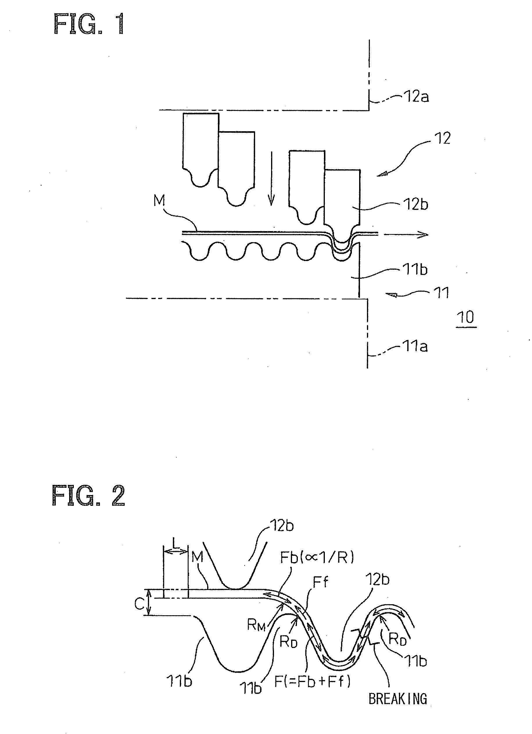
[0066]A first embodiment of the present invention for a method for a bending process will be explained with reference to the drawings. A thin metal plate, which can be easily and plastically deformed, is used as a material to be processed.

[0067]Such a material, which has relatively a small specific gravity and which is flexible, capable of plastic deformation and malleable (for example, a light metal such as aluminum) is used as the thin metal plate.

[0068]In the present embodiment, an example for manufacturing a corrugated fin, which is used in a radiator for a vehicle engine, will be explained.

[0069]The corrugated fin is made of metal plate and formed in a waveform, wherein the wave-formed portions (the corrugated portions) are arranged at equal intervals. The corrugated fins are arranged between neighboring tubes, through which working fluid (such as, engine cooling water, refrigerant or the like) flows, so as to enhance radiation of heat from the working fluid flowing in the tube...

second embodiment

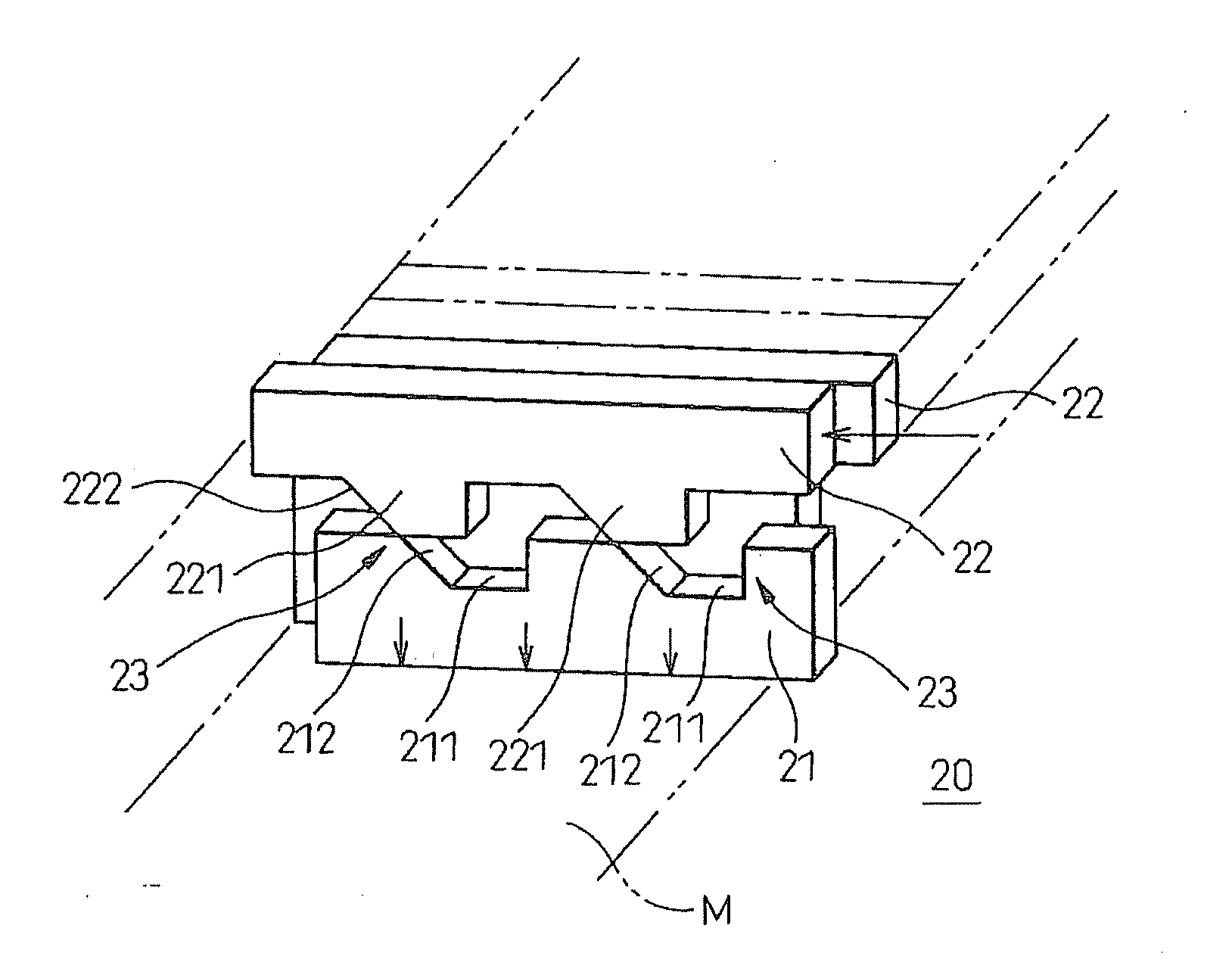
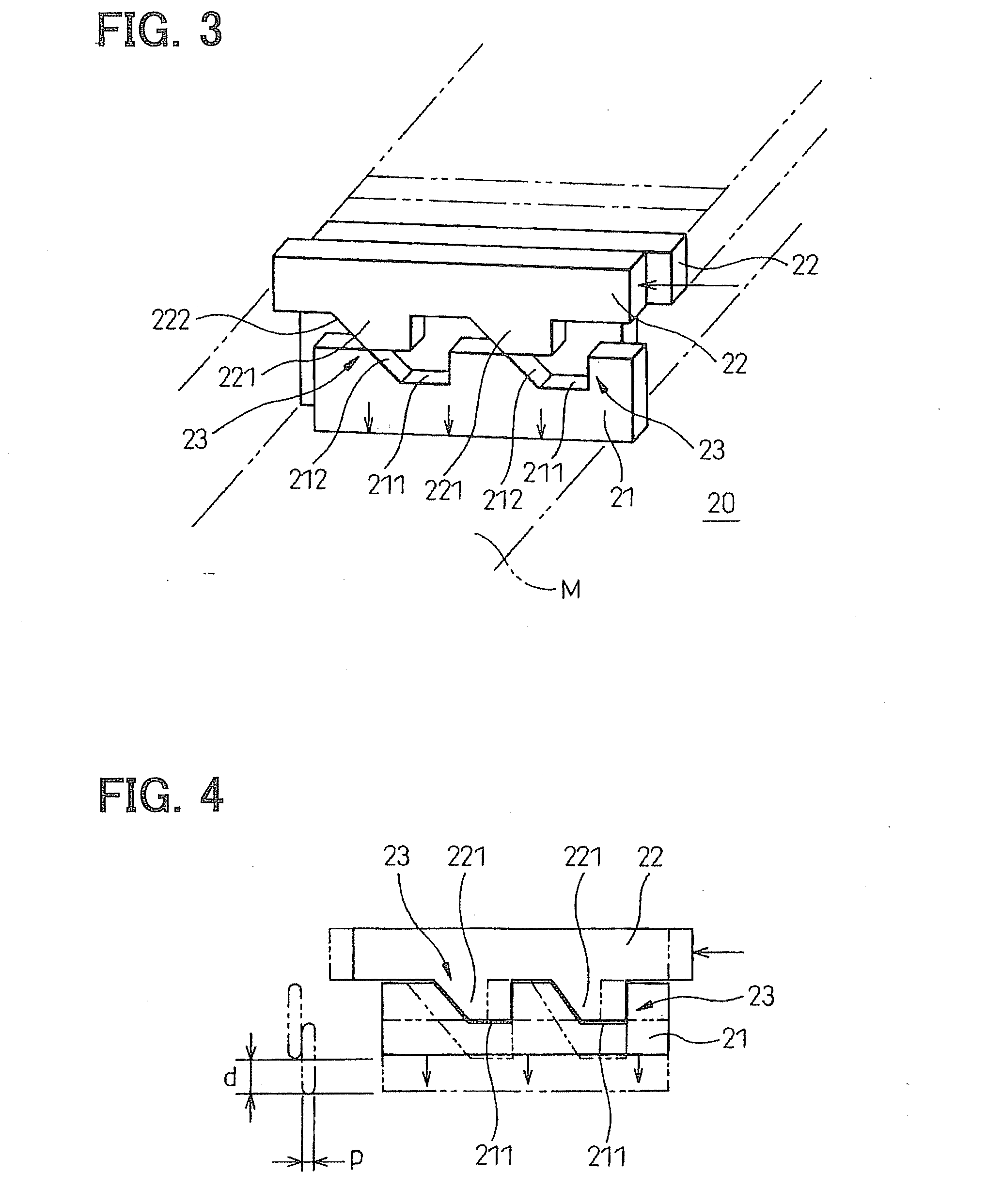
[0096]A processing machine 20 of a second embodiment is shown in FIG. 3. According to the processing machine 20, a movable cam is moved in a cam operating direction, which is perpendicular to a direction of movement of the material M, in order to move the press punch in a punch operating direction, which is a direction perpendicular to the plane of the material M. More in detail, the movable cam is moved at a back side (an upper side in FIGS. 3 and 4) of the press punch in the cam operating direction, so that the press punch is pushed down by a pushing surface of the movable cam. The pushing surface is inclined at an angle of about 45 degree with respect to a line of the cam operating direction.

[0097]The processing machine 20 has multiple movable dies 21 (the press punches) neighboring to each other, each of which is movable in the punch operating direction perpendicular to the plane of the material M. Although not shown in the drawing, the processing machine 20 has a lower die simi...

third embodiment

[0107]A processing machine 30 of a third embodiment is shown in FIG. 5.

[0108]The processing machine 30 has multiple first and second press punches 31 and 32, which are respectively arranged in the direction of the movement of the material (the thin metal plate) M. Each of the press punches 31 and 32 extends in the direction perpendicular to the direction of the movement of the material M and has a length almost equal to a width of the material M. A forward end of each press punch 31 and 32 is directed toward the material M. Each of the press punches 31 and 32 is movable toward the material M in a vertical direction in the drawing. Each of the first press punches 31 is displaced from each of the second press punches 32 in the direction of the movement of the material M by a half pitch, so that a processing concave surface portion and a processing convex surface portion are formed between opposing forward ends of the first and second press punches 31 and 32. Multiple first and second ...


PUM

PropertyMeasurementUnit
aspect ratioaaaaaaaaaa
angleaaaaaaaaaa
pulling forceaaaaaaaaaa

Abstract

Multiple movable die portions (press punches) are respectively opposing to multiple fixed die portions (block members). Each of the press punches is sequentially pushed down with a predetermined time difference to the corresponding block member to continuously carry out press work to a material inserted into a press-work area between the press punches and the block members. A clearance is formed between a forward end of the press punch and a forward end of the block member at a position shortly before a press-work operating position in order to control a pulling force of the material, so that a shape distortion can be avoided.

Description

CROSS REFERENCE TO RELATED APPLICATION[0001]This application is based on Japanese Patent Application No. 2009-119123 filed on May 15, 2009, the disclosure of which is incorporated herein by reference.FIELD OF THE INVENTION[0002]The present invention relates to a method for a bending process and a processing machine thereof, which is preferably applied to, for example, a manufacturing process of a corrugated fin for a heat exchanger.BACKGROUND OF THE INVENTION[0003]A bending process for a corrugated product is known in the art, for example, as disclosed in the following patent publications:[0004]Patent Publication No. 1: JP Patent Publication No. 2008-087033;[0005]Patent Publication No. 2: JP Patent Publication No. 2006-136896;[0006]Patent Publication No. 3: JP Patent Publication No. 2003-115567;[0007]Patent Publication No. 4: JP Patent Publication No. 2006-015388;[0008]Patent Publication No. 5: JP Patent Publication No. H11-179438;[0009]Patent Publication No. 6: JP Patent Publicatio...

Claims


Application Information

Patent Timeline
Patent Type & Authority Applications(United States)
IPC IPC(8): B21D13/02
CPCB21D53/022B21D13/02
Inventor OTSUBO, HIDEMASAMITSUKAWA, KAZUHIROSHIOMI, TOMOHIRO
Owner DENSO CORP
Why Eureka
Try Eureka