Power supply circuit for multi-path light-emitting diode (LED) loads

a power supply circuit and load technology, applied in the field of power electronics, can solve the problems of increasing damage to the driver circuit, increasing etc., and achieve the effects of reducing current stress in the circuit, improving reliability of the circuit, and reducing the cost of the circui

Active Publication Date: 2013-05-23
INVENTRONICS HANGZHOU
View PDF2 Cites 15 Cited by
  • Summary
  • Abstract
  • Description
  • Claims
  • Application Information

AI Technical Summary

Benefits of technology

[0046]In the power supply circuit for multiple LED loads according to the embodiments of the invention, the first switch tube is connected in parallel to the second diode, and the second switch tube is connected in parallel to the fourth diode; the on states of the second diode and the fourth diode are controlled by controlling the on / off-states of the first switch tube and the second switch tube. When the system is in a normal state, the first switch tube and the second switch tube are both switched off; and when one of loads needs to be turned off, a corresponding switch tube is switched on such that the diode connected in parallel to the corresponding switch tube is shorted. Thus, strong impulse current in filter capacitor due to the direct short of any of the loads is avoided, such that the current stress in the circuit is reduced, the reliability of the circuit is improved, and the cost of the circuit is reduced.

Problems solved by technology

In the circuit shown in FIG. 1, if one of the LED loads is opened and the other path of the LED loads is ensured to operate normally, an abnormal overvoltage will occur at the output of the opened load, such that the driver circuit will be damaged.
However, the open circuit protection circuit K has the following disadvantages: when the output voltage is abnormal, the thyristor is turned on, and short-circuit discharge of an output filter capacitor (Co3, Co4) will cause a large impulse current, such that current stress in the circuit is increased, the cost of the circuit is increased and the reliability of the circuit is reduced.

Method used


Image

  • Power supply circuit for multi-path light-emitting diode (LED) loads
  • Power supply circuit for multi-path light-emitting diode (LED) loads
  • Power supply circuit for multi-path light-emitting diode (LED) loads

Examples


first embodiment

[0060]A circuit diagram of a power supply circuit for multiple LED loads according to the invention is shown in FIG. 5.

[0061]The power supply circuit for multiple LED loads according to this embodiment includes: a first filter capacitor Co1, a second filter capacitor Co2, a first switch tube Q1, a second switch tube Q2, a first rectifier branch and a second rectifier branch;

[0062]inputs of the first rectifier branch and inputs of the second rectifier branch are connected to a high-frequency AC power source; as shown in FIG. 5, an anode of a first diode D1 and a cathode of a second diode D2 are both connected to one terminal of the high-frequency AC power source, and a left terminal of a first capacitor Cb is connected to the other terminal of the high-frequency AC power source. It is to be noted that in each of the following embodiments the first rectifier branch and the second rectifier branch connect to the high-frequency AC power source in a way identical to that in this embodime...

second embodiment

[0072]A circuit diagram of a power supply circuit for multiple LED loads according to the invention is shown in FIG. 6.

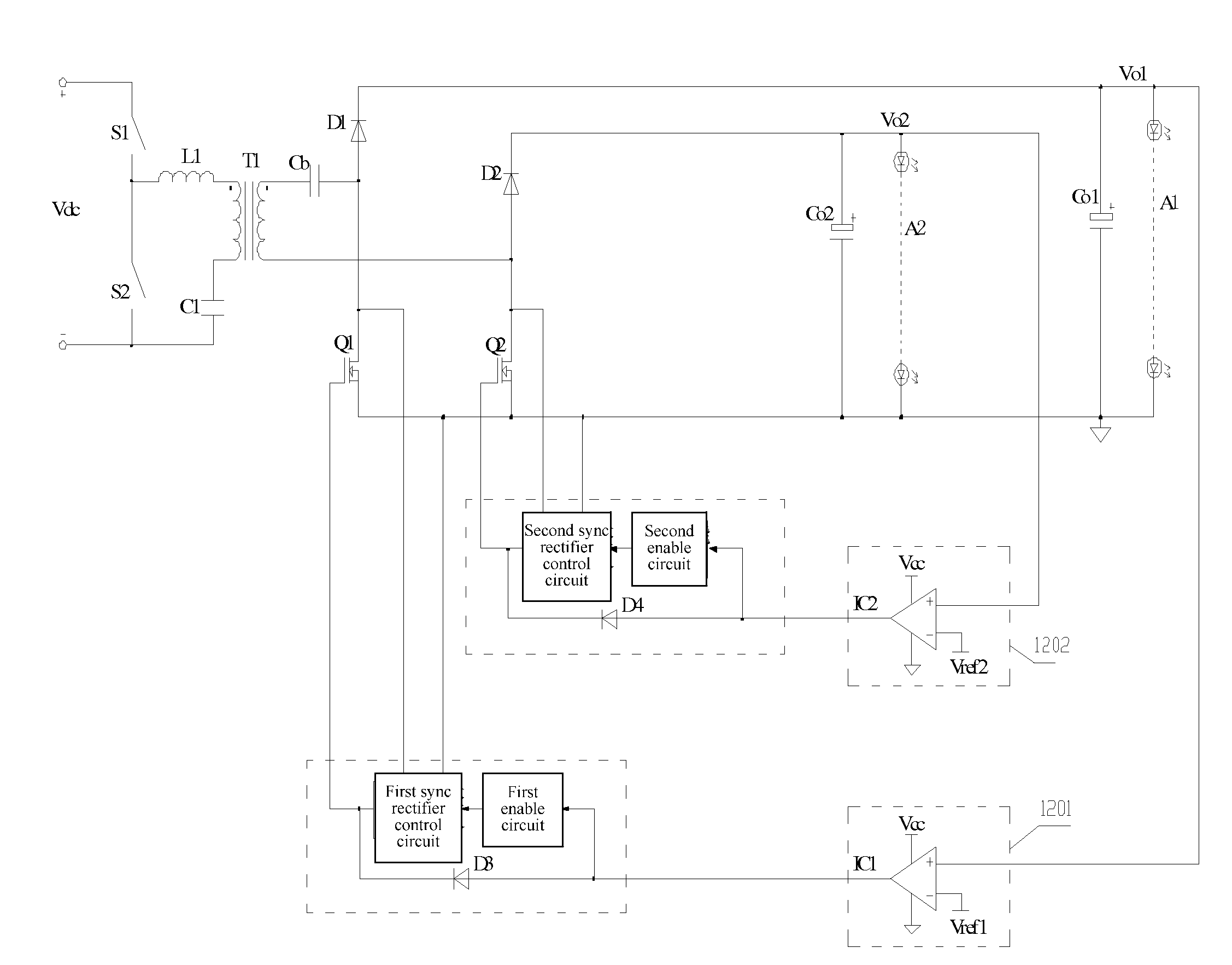
[0073]The power supply circuit for multiple LED loads according to this embodiment further includes a first control circuit 601 and a second control circuit 602.

[0074]An input of the first control circuit 601 is connected to an output of the first LED load A1, and an output of the first control circuit 601 is connected to a control terminal of the first switch tube Q1.

[0075]The first control circuit 601 is configured to detect an output voltage of the first LED load A1, and switch on the first switch tube Q1 when the output voltage of the first LED load A1 is higher than a first preset voltage.

[0076]An input of the second control circuit 602 is connected to a positive output of the second LED load A2, and an output of the second control circuit 602 is connected to a control terminal of the second switch tube Q2.

[0077]The second control circuit 602 is configured to d...

third embodiment

[0079]It is to be noted that in this embodiment of the invention, the first control circuit 601 is a first comparator IC1, and the second control circuit 602 is a second comparator IC2, as shown in FIG. 7, which is a circuit diagram of a power supply circuit for multiple LED loads according to the invention.

[0080]A positive input of the first comparator IC1 is connected to a positive output of the first LED load A1, a negative input of the first comparator IC1 is connected to the first preset voltage Vref1, and an output of the first comparator IC1 is connected to the a control terminal of the first switch tube Q1; and

[0081]a positive input of the second comparator IC2 is connected to a positive output of the second LED load A2, a negative input of the second comparator IC2 is connected to the second preset voltage Vref2, and an output of the second comparator IC2 is connected to a control terminal of the second switch tube Q2.

[0082]It is to be noted that the first preset voltage Vr...


PUM


Abstract

The present invention discloses a power supply circuit for multi-path light-emitting diode (LED) loads. The two ports of the second diode are connected in parallel with the first switch tube, and the two ports of the forth diode are connected in parallel with the second switch tube. The conduction mode of the second and forth diodes is controlled by controlling the switch status of the first and second switch tubes. When the system is on a normal state, the first and second switch tubes are both switched off. When the load output of any path needs to be turned off, the corresponding switch tube should be controlled to switch on, which makes the diode connected in parallel with the switch tube short-circuited. The present invention can avoid a strong impulse current produced in filtering capacitor when the load of any path is directly short-circuited. Therefore, the present invention can reduce the current stress in circuits, improve the reliability of circuits, and reduce the cost.

Description

CROSS REFERENCE TO RELATED APPLICATION[0001]This application claims the priority to Chinese patent application No. 201010246507.7, entitled “POWER SUPPLY CIRCUIT FOR MULTI-PATH LIGHT-EMITTING DIODE (LED) LOADS”, filed with the State Intellectual Property Office of PRC on Aug. 3, 2010, which is incorporated herein by reference in its entirety.FIELD OF THE INVENTION[0002]The present invention relates to the technical field of power electronics, and more particularly to a power supply circuit for multiple LED loads.BACKGROUND OF THE INVENTION[0003]A constant current driver circuit for two LED loads (Chinese patent application No. 200910155848.0) is shown in FIG. 1, in which a capacitor Cb can maintain the currents of two LED loads (A1 and A2) to be equal. In FIG. 1 the constant current driver circuit for only two LED loads is shown. A constant current driver circuit for more than two LED loads can be implemented as the circuits shown in FIG. 2 and FIG. 3, in which current sharing among...

Claims


Application Information

Patent Timeline
Patent Type & Authority Applications(United States)
IPC IPC(8): H05B37/02H05B44/00H05B45/50
CPCH05B33/0887H05B33/0815H05B37/02H05B45/50H05B47/10H05B45/385H05B45/39
Inventor GE, LIANG'AN
Owner INVENTRONICS HANGZHOU
Why Eureka
Try Eureka