Remote environment inspection apparatus and method

a remote environment and inspection apparatus technology, applied in the direction of magnetic property measurement, material magnetic variables, instruments, etc., can solve the problems of large mismatch between the acoustic impedance of air and the acoustic impedance of test materials, the inability to detect the presence of dirt and debris, etc., to achieve the effect of changing the magnetic field strength

Active Publication Date: 2013-05-23
SONOMATIC
View PDF12 Cites 23 Cited by
  • Summary
  • Abstract
  • Description
  • Claims
  • Application Information

AI Technical Summary

Benefits of technology

[0036]Most preferably the movably mounted permanent magnet comprises a permanent magnet rotatably mounted with respect to the poles of the magnetic yoke. Relative rotation of the permanent magnet and the magnetic yoke therefore provides a means for varying the DC magnetic field generated within the test component at a particular location on the surface of the test component.
[0037]The rotatable

Problems solved by technology

A number of different ultrasonic tools and methods are available, but there are drawbacks and deficiencies associated with their operation.
Firstly, ultrasonic tools operating according to the contact method require good coupling between the contact transducers and the test object, and the large mismatch in the acoustic impedance of air and the acoustic impedance of the test material must be overcome.
Ultrasonic inspection tools are also highly sensitive to dirt and debris, which can interfere with the acoustic coupling and/or show up as anomalous features or artefacts in the analysed data.
This means that ultrasonic inspection may not be practicable for some oil and gas exploration environments.
The method is therefore limited to use with ferromagnetic materials.
At low speeds the coils can totally miss long areas of wall loss if the changes in wall thickness are gradual.
For pipe types with high wall thickness or thick coating, this is often not possible.
The MFL measurement is thus limited to use with certain pipe types.
However, ECT does have some inherent limitations.
For example the techniques are only applicable to conductive materials; they require the surface to be tested to be accessible to the probe; and they are limited in the depth of penetration into the material being tested that can be achieved.
As a result with conventional PSET techniques the identified defect often needs to be determined or corroborated by an alternative NDT technique, for example by ultrasound testing, since

Method used


Image

  • Remote environment inspection apparatus and method
  • Remote environment inspection apparatus and method
  • Remote environment inspection apparatus and method

Examples


Embodiment Construction

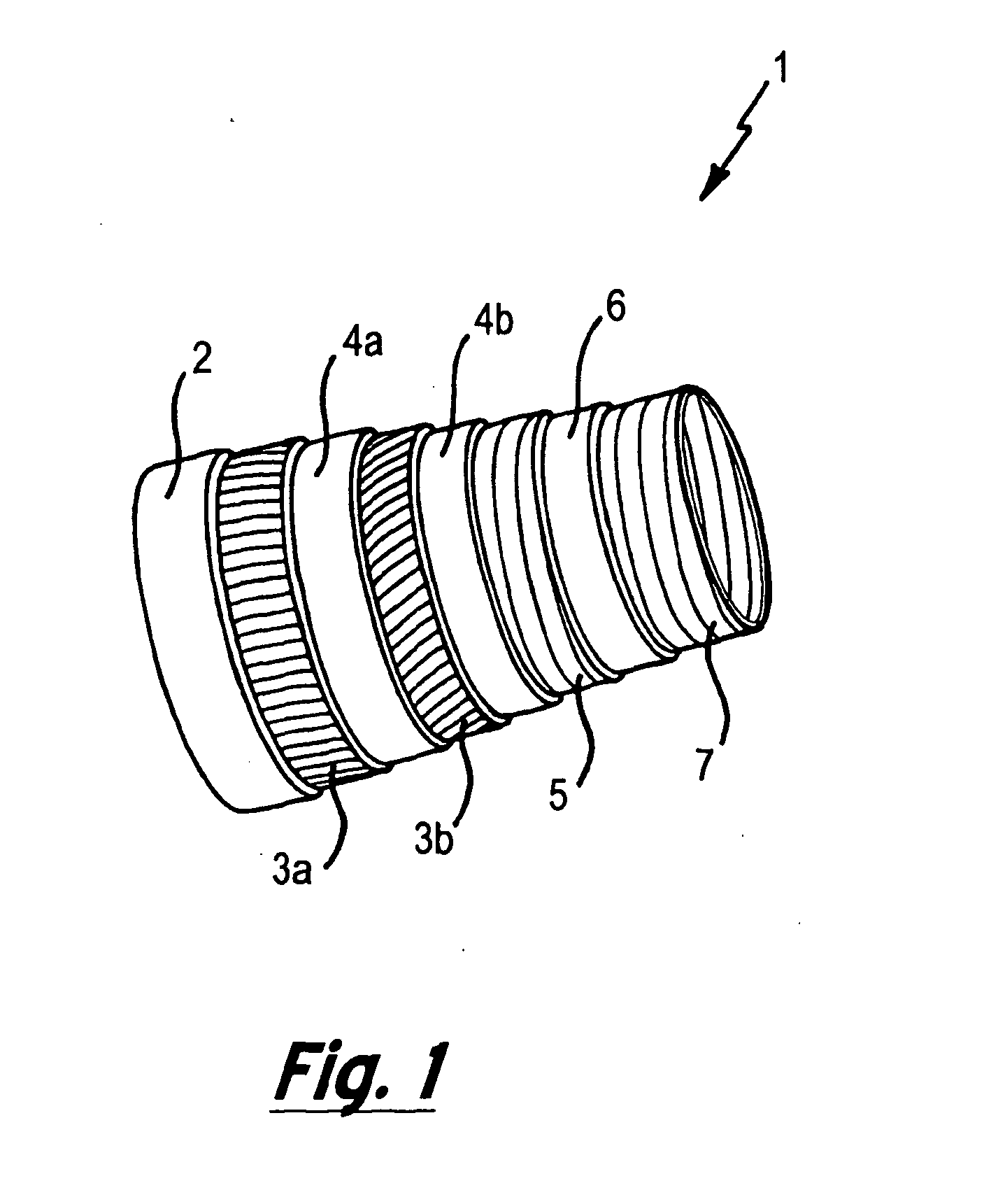
[0097]For ease of understanding the present invention will be described with reference to use with a flexible riser, a schematic representation of which is provided in FIG. 1. However, it will be appreciated by those skilled in the art that aspects of the present invention are not limited to use with such components.

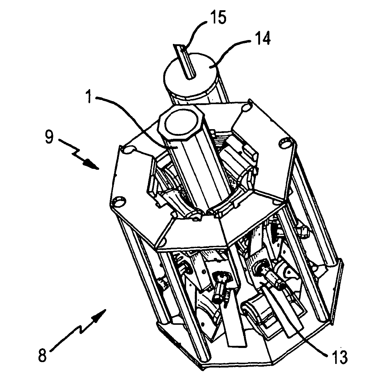
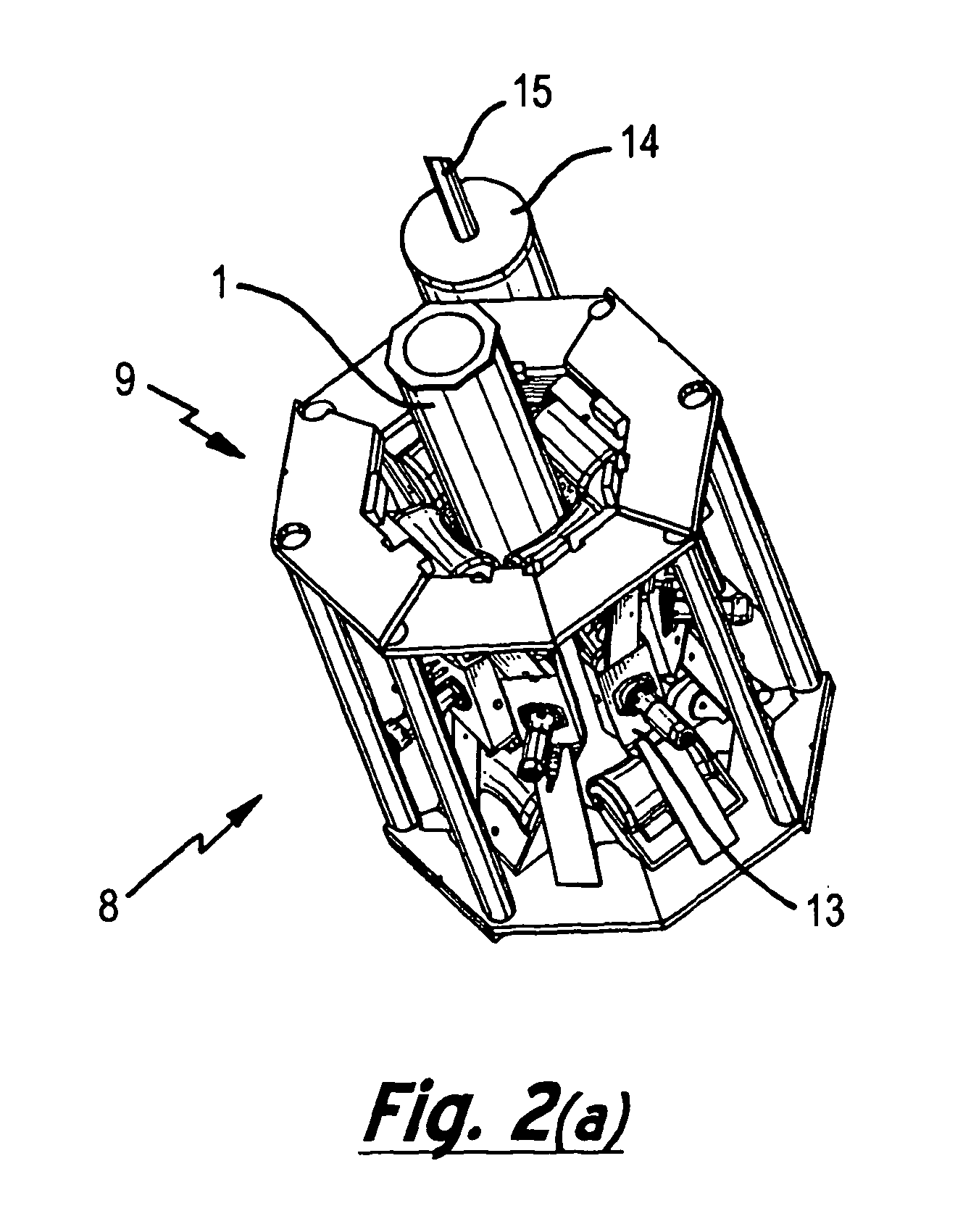
[0098]Perspective views of an inspection tool 8 in accordance with an embodiment of the present invention are provided in FIG. 2. In particular, FIG. 2(a) presents the inspection tool 8 in a closed configuration around a flexible riser 1 while FIG. 2(b) presents the inspection tool 8 in an open configuration.

[0099]The inspection tool 8 can be seen to comprise a clamp 9 that in the closed configuration of FIG. 2(a) fully encircles the flexible riser 1. The clamp 9 comprises six separate clamp sections 10a to f that are pivotally mounted to each other. A mechanical clasp 11 provides a means for securing the first clamp section 10a to the sixth clamp section 10f when the in...


PUM


Abstract

An inspection tool for the non-destructive testing of a test component made of an electrically conductive material is described. The inspection tool employs movably mounted permanent magnets, which provides a means for generating a variable DC magnetic field within the test component, and eddy current probes so as to provide a means for performing a partial saturation eddy current test upon the test component. The eddy current probe preferably comprises an integrated magnetic field sensor which increases the accuracy and flexibility of the modes of operation of the described apparatus and methods. The described apparatus and methods are particularly suited for the inspection of tubular components that are often remotely located within the oil and gas exploration and production industries.

Description

[0001]The present invention relates to non-destructive testing, and in particular to a method and apparatus for the inspection of electrically conductive components. Applications of the invention include the inspection of tubular components that are often remotely located within the oil and gas exploration and production industries.[0002]A variety of components are employed within the oil and gas industry, such as casings, production tubing, pipelines, flexible risers and steel wire ropes. In order to monitor the structural integrity of these components a variety of non-destructive testing techniques are known for the detection and identification of defects and / or fatigue in the external wall of these tubular components.[0003]One such non-destructive testing technique known in the art is ultrasound inspection, for example as described in U.S. Pat. No. 4,162,635 or US patent publication no. US 2008 / 0313915. The ultrasound signal is transmitted into the tubing wall, and analysis of th...

Claims


Application Information

Patent Timeline
IPC IPC(8): G01N27/90
CPCG01N27/904G01N27/9033G01N27/9006G01N27/902G01B7/10G01B7/24G01B7/34G01N27/9046G01N27/9053G01R33/1223G01R33/12
Inventor BOENISCH, ANDREAS
Owner SONOMATIC
Why Eureka
Try Eureka