Radiation generating tube and radiation generating apparatus using the same
a radiation generating apparatus and generating tube technology, applied in the field of radiation generating tubes, can solve problems such as the ability to improve the voltage withstanding capacity, and achieve the effect of high voltage withstanding capability
- Summary
- Abstract
- Description
- Claims
- Application Information
AI Technical Summary
Benefits of technology
Problems solved by technology
Method used
Image
Examples
first example
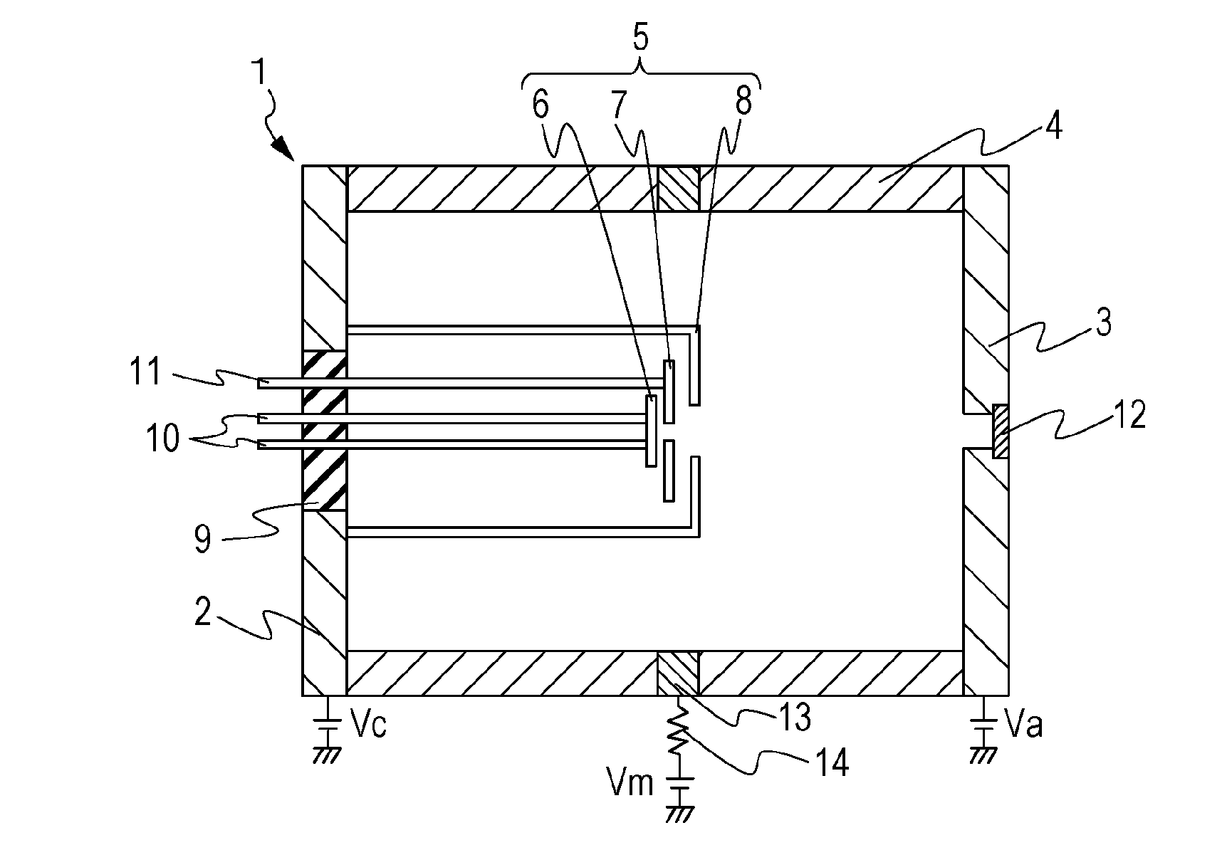
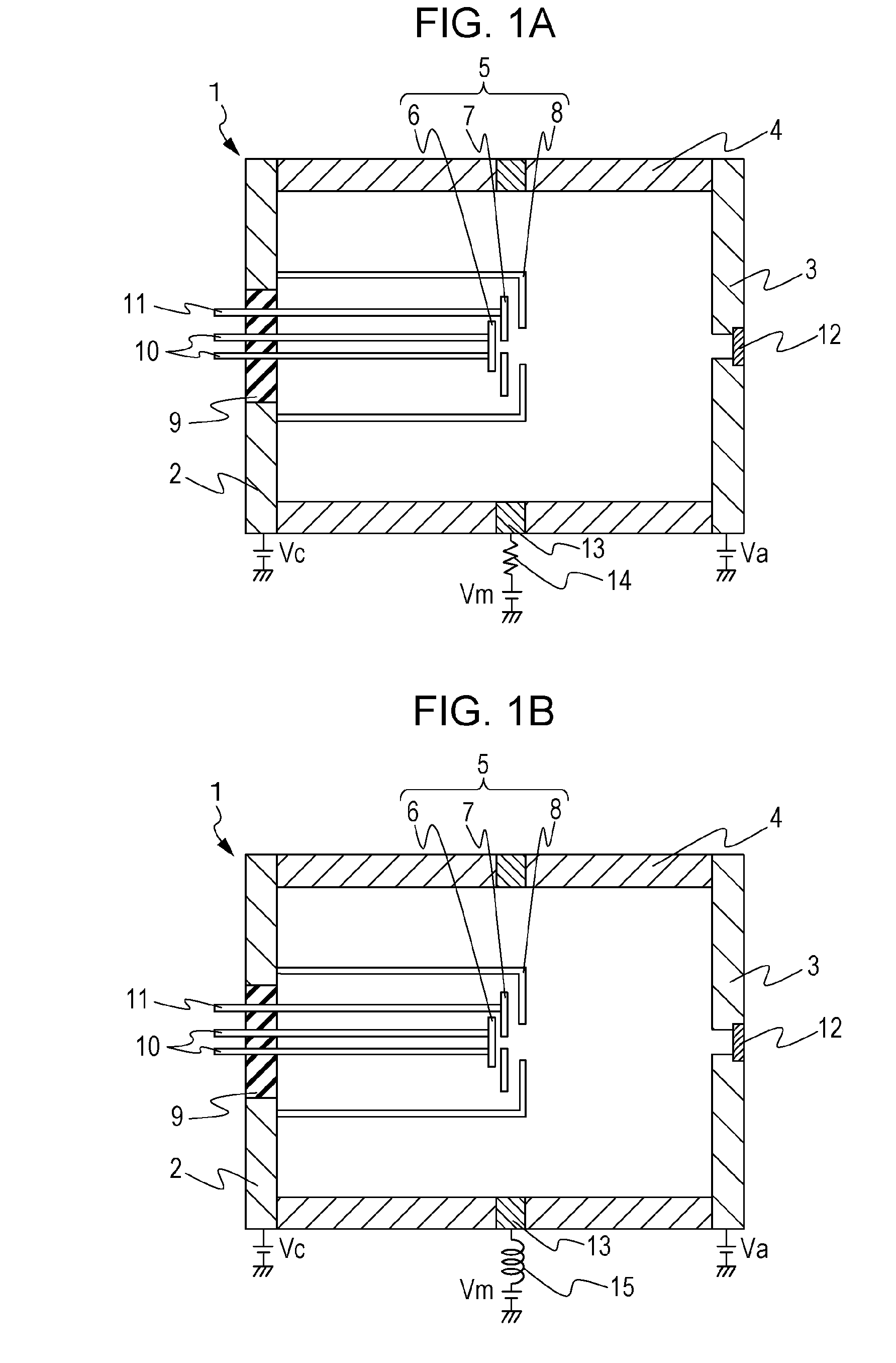
[0037]A first example, which is one of the exemplary configurations described above, will be described with reference to FIG. 1A. FIG. 1A is a schematic cross-sectional view of a radiation generating tube 1 along a central axis of a tubular side wall 4. A radiation generating tube 1 of the present example includes a cathode 2, an anode 3, the tubular side wall 4, an electron gun structure 5, an insulating member 9, a terminal for driving the electron source 10, a terminal for grid electrode 11, a target 12, an electrical potential defining member 13 and an electrical resistance member 14. The electron gun structure includes an electron source 6, a grid electrode 7 and a focusing electrode 8.
[0038]The cathode 2, the anode 3 and the electrical potential defining member 13 are made of Kovar. The tubular side wall 4 and the insulating member 9 are made of alumina. These constituents are fixed to each other by welding. The tubular side wall 4 is cylindrical in shape. The electron source ...
second example
[0045]A second example differs from the first example in that an inductor 15 is provided in place of the electrical resistance member 14 as illustrated in FIG. 1B.
[0046]The same examination as that of the first example is carried out using this radiation generating tube 1 with the inductance value of the inductor 15 being set to 10 mH. A discharge current which flows into the focusing electrode 8 from the electrical potential defining member 13 is reduced in the same manner as in the first example.
[0047]Further, in the same manner as in the first example, radiation is emitted successfully by the radiation generating apparatus 17 manufactured using the radiation generating tube 1 without any disturbance of electrical discharge.
third example
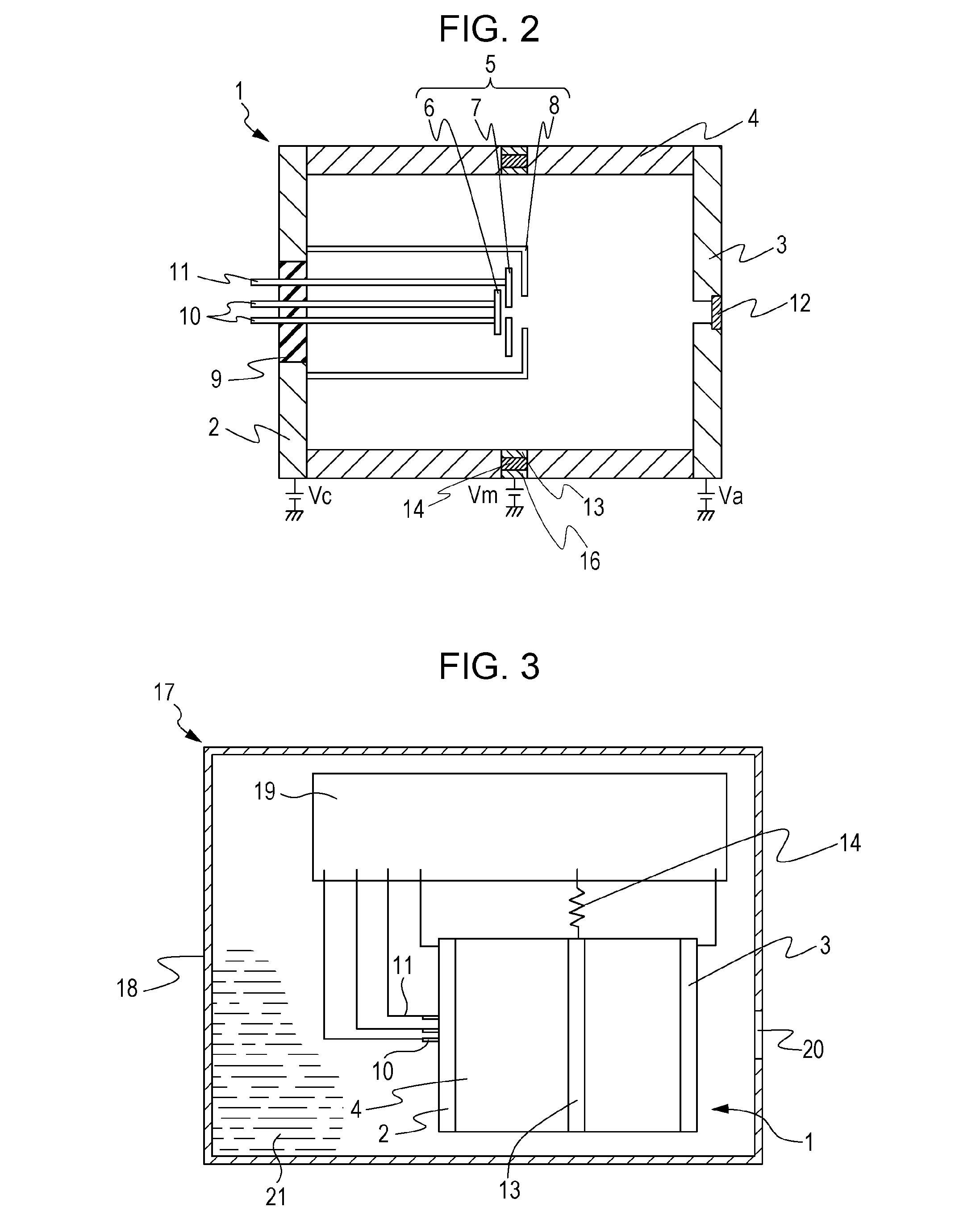
[0048]A third example differs from the first example in that, as illustrated in FIG. 2, the electrical resistance member 14 is disposed between the electrical potential defining member 13 and an electrical potential defining member 16, which is another electrical potential defining member. The electrical resistance member 14 is made of a conductive ceramic in which metallic oxide particles are dispersed. The ceramic material is machined into a ring shape. The electrical potential defining member 13 is attached to the ring-shaped ceramic material on an inner wall side of the tubular side wall 4. The electrical potential defining member 16 is attached to the ceramic material on the outer wall side of the tubular side wall 4. The thus-prepared member is formed to connect the tubular side wall 4 and the electrical potential defining member 16. The electric resistance value of the electrical resistance member 14 is set to about 1MΩ.
[0049]In the thus-manufactured radiation generating tube...
PUM
 Abstract
Description
Claims
Application Information
 - R&D
- Intellectual Property
- Life Sciences
- Materials
- Tech Scout
- Unparalleled Data Quality
- Higher Quality Content
- 60% Fewer Hallucinations
Browse by: Latest US Patents, China's latest patents, Technical Efficacy Thesaurus, Application Domain, Technology Topic, Popular Technical Reports.
© 2025 PatSnap. All rights reserved.Legal|Privacy policy|Modern Slavery Act Transparency Statement|Sitemap|About US| Contact US: help@patsnap.com


