Eureka AIR delivers breakthrough ideas for toughest innovation challenges, trusted by R&D personnel around the world.

Reactor and manufacturing method for reactor

a manufacturing method and reactor technology, applied in the field of reactors, can solve the problems of difficult lid design, difficult to completely prevent the iron powder at the opening portion from contacting air, and so as to prevent the rusting of the magnetic powder, and prevent the rusting of the magnetic core. , the effect of simple structur

Inactive Publication Date: 2013-05-30
SUMITOMO ELECTRIC IND LTD
View PDF8 Cites 14 Cited by
  • Summary
  • Abstract
  • Description
  • Claims
  • Application Information

AI Technical Summary

Benefits of technology

The present invention provides a reactor with a surface layer that prevents rusting and is not separated during operation. The surface layer is formed on the opening portion of the case side of the magnetic core and is continuous with the magnetic core without any interface. The surface layer has similar resin to the magnetic core and contains less magnetic powder, so there is no need for a separate covering member. This simplifies the reactor structure, reduces components, and maintains magnetic characteristics. The manufacturing process is also simplified, improving productivity.

Problems solved by technology

Thus, magnetic characteristics of the magnetic core may be degraded due to corrosion of part of the iron powder caused by contact of the iron powder with air.
Furthermore, even when the lid is provided on the case, it is very difficult to completely prevent the iron powder at the opening portion from contacting air.
The reason of this is that designing of the lid, which can seal the opening portion of the case without a gap and does not allow a space to be formed between the lid and the magnetic core, is very difficult.

Method used


Image

  • Reactor and manufacturing method for reactor
  • Reactor and manufacturing method for reactor
  • Reactor and manufacturing method for reactor

Examples


first embodiment

[0047]

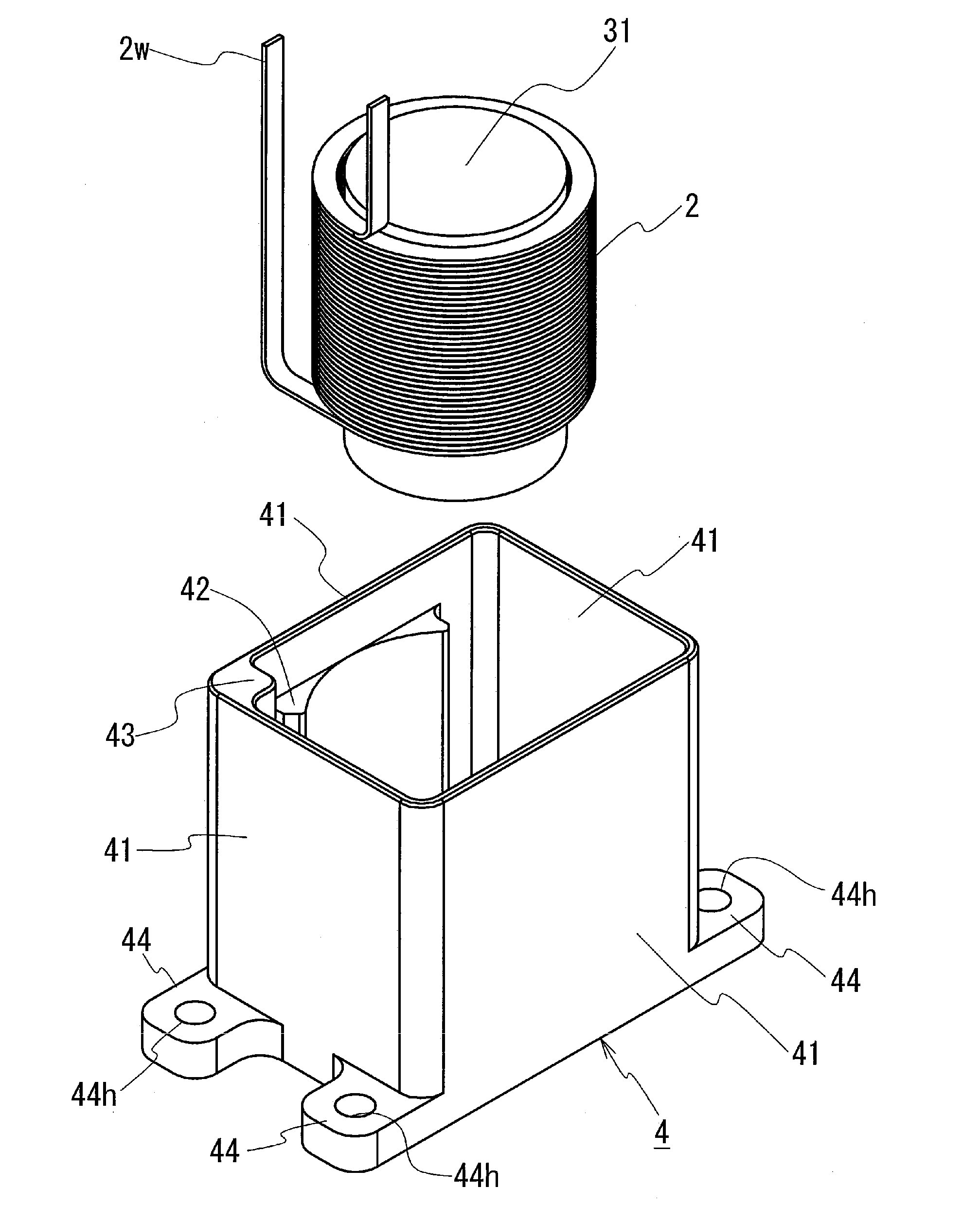
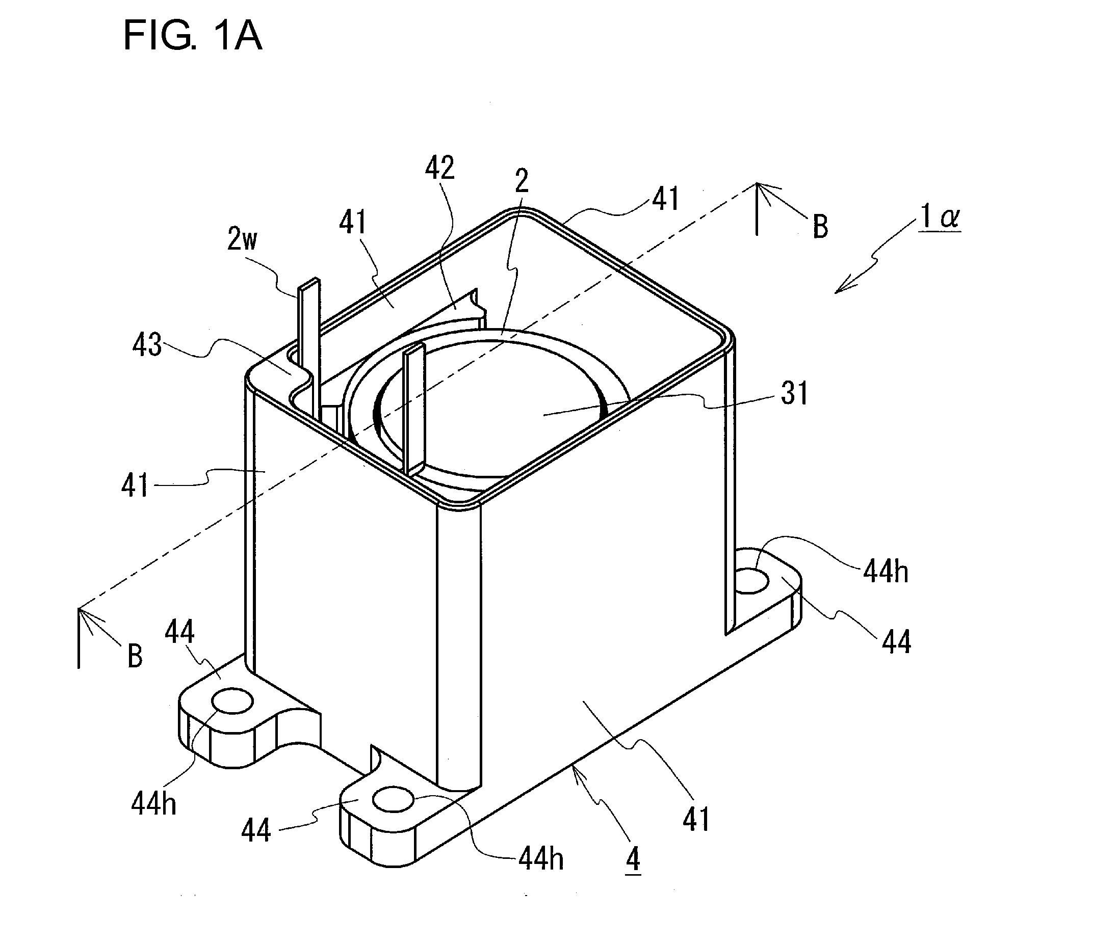
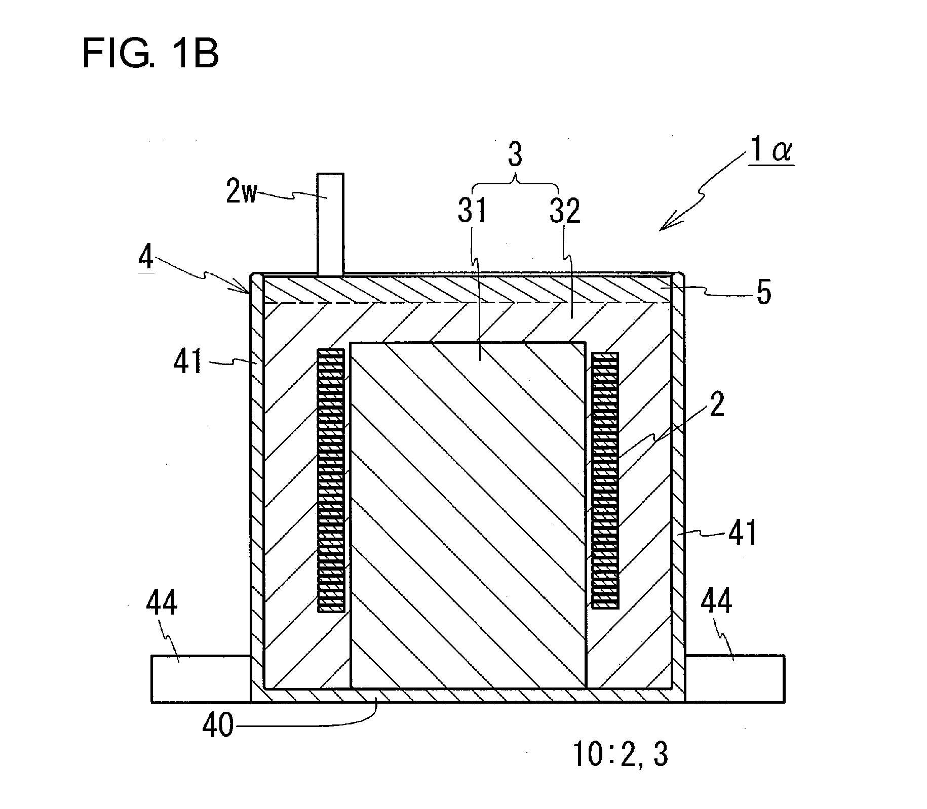
[0048]As illustrated in FIGS. 1A and 1B, a reactor 1α is a so-called pot-type reactor and includes a coil 2 and a magnetic core 3. The coil 2 is formed by winding a wire 2w. The coil 2 is disposed in the magnetic core 3. The reactor 1α also includes a case 4 that houses an assembly 10 formed of the coil 2 and the magnetic core 3. The magnetic core 3 includes an internal core portion 31 and a core coupling portion 32. The internal core portion 31 is inserted through the coil 2. The core coupling portion 32 is disposed on an outer periphery of the coil 2 and connected to the internal core portion 31. Both the core portions 31 and 32 form a closed magnetic circuit. The core coupling portion 32 is formed of a molded solid body containing magnetic powder and resin. The coil 2 is sealed in the case 4 with the outer periphery thereof substantially covered by the core coupling portion 32. A surface layer 5 is provided on a surface of the magnetic core 3 on the opening portion of the c...

second embodiment

[0130]As illustrated in FIG. 3, the difference between the first embodiment and a second embodiment is that the coil 2 and the internal core portion 31 is housed in the case 4 such that the axial direction of the coil 2 is parallel to the bottom surface 40 of the case 4 (this form of arrangement is referred to as a horizontal arrangement hereafter). The difference between the first embodiment and the second embodiment is described below.

[0131]The magnetic core 3 of a reactor 1β of the present example includes the internal core portion 31 and the core coupling portion 32. The internal core portion 31 is inserted through the coil 2 such that the axial direction thereof is parallel to the bottom surface 40 of the case 4 so that the direction of the internal core portion 31 matches the direction of the coil 2. The combination of the coil 2 and the internal core portion 31 are integrally formed with the outer periphery thereof covered with the core coupling portion 32 such that both the ...


PUM

PropertyMeasurementUnit
Timeaaaaaaaaaa
Magnetismaaaaaaaaaa

Abstract

A reactor 1α includes a coil 2 formed by winding a wire 2w, a magnetic core 3 that is disposed inside and outside of the coil 2 and forms a closed magnetic circuit, and a case 4 that has an opening portion and a bottom surface 40 that opposes the opening portion and that houses an assembly 10 of the coil 2 and the magnetic core 3. At least the opening portion of the case 4 side of the magnetic core 3 is formed of a molded solid body that contains magnetic powder and resin. A surface layer 5, which prevents the magnetic powder from rusting, is provided on a surface of the magnetic core 3 on the opening portion of the case 4 side. The surface layer 5 has a resin portion formed of resin similar to the resin contained in the magnetic core 3. The resin portion is formed so as to be continuous with the resin contained in the magnetic core 3 without an interface formed therebetween.

Description

TECHNICAL FIELD[0001]The present invention relates to reactors used for components of power conversion devices such as on-vehicle DC-DC converters and relates to a manufacturing method for the rectors. In particular, the present invention relates to a reactor, which includes a small number of components, has a simple structure, and uses a magnetic core that is not easily degraded.BACKGROUND ART[0002]A reactor is one of components in a circuit that operates to increase or decrease voltage. This reactor is utilized in a converter installed in a vehicle such as a hybrid automobile. The structure of such a reactor is described, for example, in Patent Literature 1.[0003]The reactor described in Patent Literature 1 includes a coil and a magnetic core, which is a so-called pot-type core having an E-E shaped section. The magnetic core includes an internal core portion, an external core portion, and a core coupling portion. The internal core portion is disposed at an inner periphery of the c...

Claims


Application Information

Patent Timeline
IPC IPC(8): H01F27/02H01F41/02H01F3/08
CPCH01F27/23H01F41/0246H01F27/022H01F37/00H01F3/08H01F27/02
Inventor INABA, KAZUHIRO
Owner SUMITOMO ELECTRIC IND LTD
Why Eureka
Eureka Blog
Learn More