
Power-economizing, integral electric vehicle drive mechanism with independent rear suspension for an electric vehicle with a multi-speed transmission capable of multiplying the torque of the electric motor at low speeds

a technology of electric vehicles and drive mechanisms, which is applied in the direction of electric propulsion mounting, manufacturing tools, and manufacturing tools, etc., can solve the problems of low speed performance, vehicle may not move at all, and the requirement may exceed the ability of electric vehicles to supply, so as to facilitate vehicle repair and manufacturing. , the effect of significantly reducing the amount of energy required to accelerate the vehicl

Inactive Publication Date: 2013-06-06
ROCHLANI VIJAY
View PDF0 Cites 8 Cited by
  • Summary
  • Abstract
  • Description
  • Claims
  • Application Information

AI Technical Summary

Benefits of technology

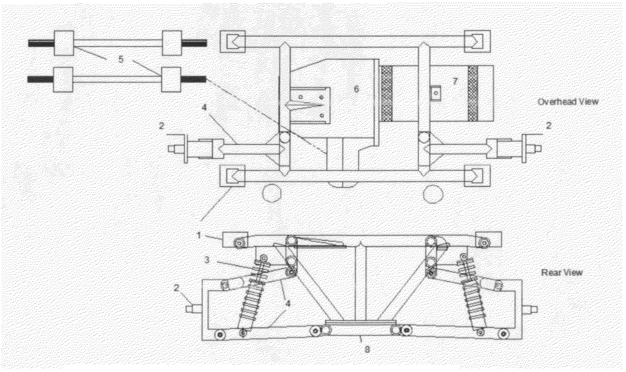
The present invention is a torque-economizing, integral electric vehicle drive mechanism with independent rear suspension for an electric vehicle with a multi-speed transmission. This invention is a significant improvement over the current state of the art because it utilizes multiple gear ratios in a multi-speed transmission at higher gear ratios to power the vehicle more economically. The transmission may be manually shifted or continuously varied between the input and output shafts of the transmission in order to achieve this invention. The electric drive axis is parallel to the driven gears in the transmission, and to the drive axles, which is a significant improvement over the typical right-angle motor alignment in the electric vehicle. The invention proposes that the multi-speed, front-wheel-drive manual or automatic transmission is placed in position to drive the rear wheels of the electric vehicle. The invention also includes a filly independent suspension in the rear of the electric vehicle, which improves the handling of the vehicle in almost all ordinary on-road conditions and some off-road conditions and may improve ground clearance over the current art.

Problems solved by technology

The weakness in this design is the very low speed performance when the electric vehicle is accelerating or beginning to move or traveling up an incline where the weight of the vehicle is multiplied by the grade for an increased resistance on the electric traction motor.
For example, in a small truck with a significant payload on a positive grade of 5%, so much torque is required to begin to move the vehicle, that this requirement may exceed the electric vehicle's ability to supply it.
The vehicle may not move at all, or may slightly move with the addition of inordinate amounts of power drawing from the storage device.

Method used


Image

  • Power-economizing, integral electric vehicle drive mechanism with independent rear suspension for an electric vehicle with a multi-speed transmission capable of multiplying the torque of the electric motor at low speeds
  • Power-economizing, integral electric vehicle drive mechanism with independent rear suspension for an electric vehicle with a multi-speed transmission capable of multiplying the torque of the electric motor at low speeds
  • Power-economizing, integral electric vehicle drive mechanism with independent rear suspension for an electric vehicle with a multi-speed transmission capable of multiplying the torque of the electric motor at low speeds

Examples


Embodiment Construction

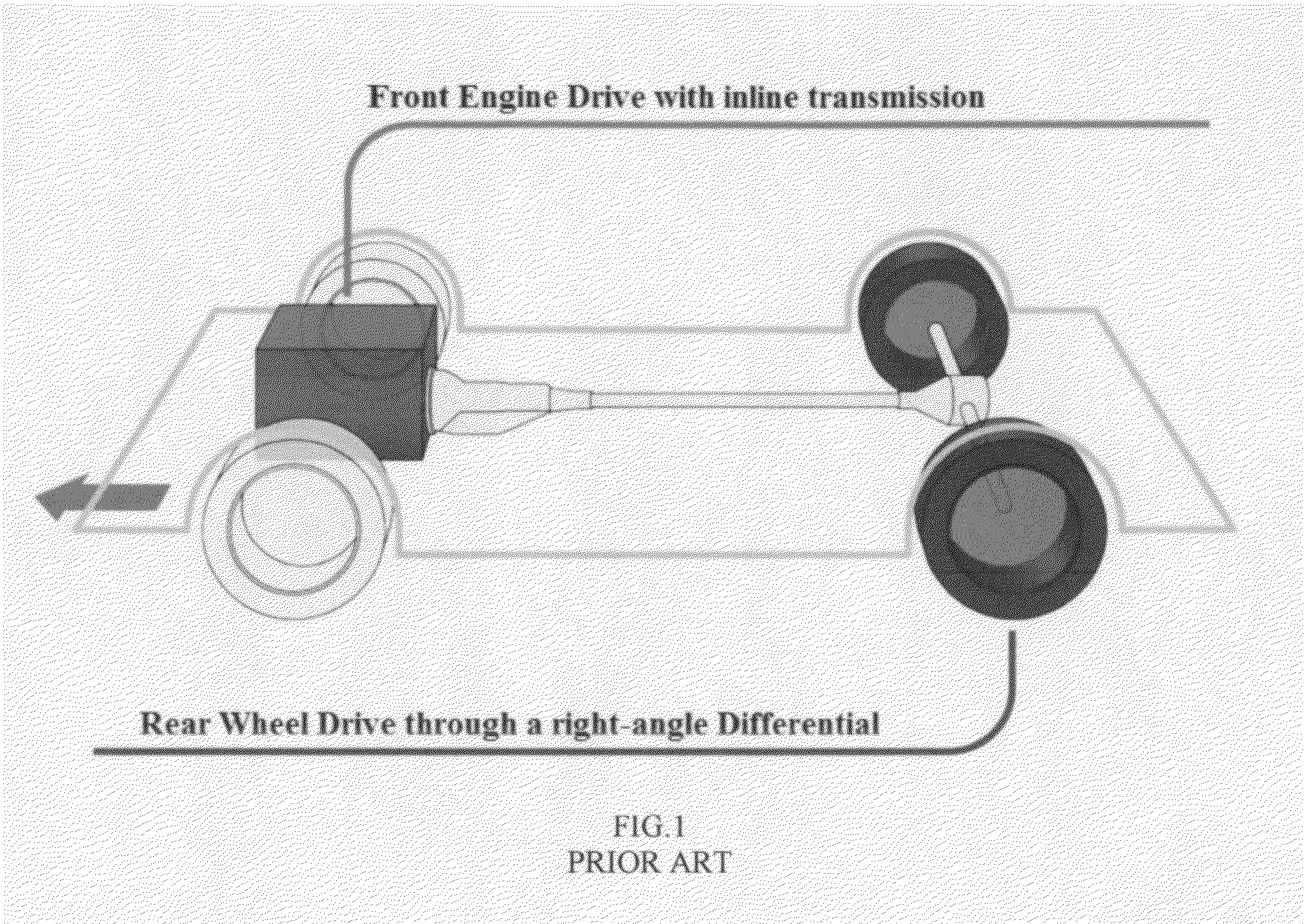
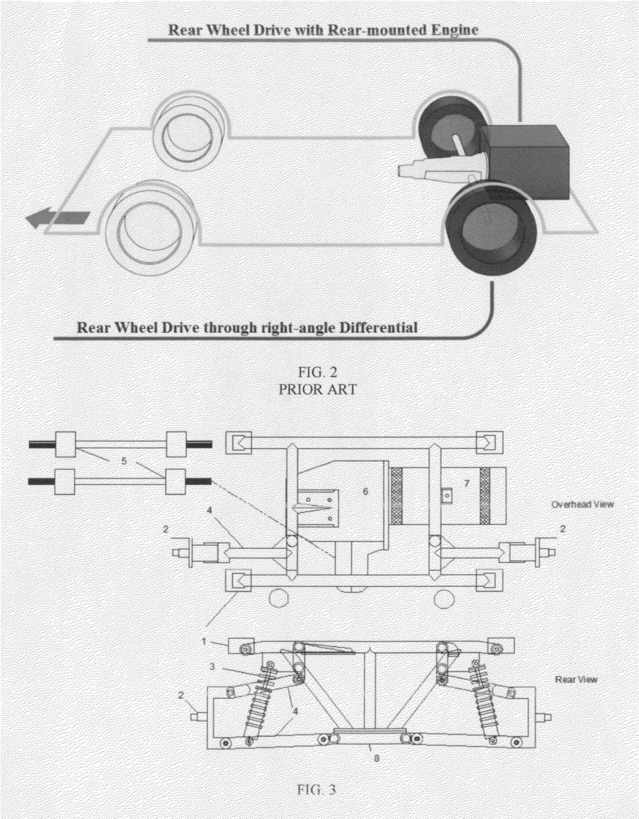
[0017]Referring now to the invention in more detail, a front engine, rear wheel drive vehicle is very common. This is mechanically inefficient as the mechanical drag of the spiral / bevel gears of the differential and the changing of the direction of the energy through a ring and pinion gear is significant and not productive toward moving the vehicle forward or backward. This results in a loss of energy. FIG. 1 shows a prior art vehicle design with the engine located in the front of the vehicle with a drive shaft delivering power to the rear wheels through a right-angle differential. FIG. 2 shows a prior art vehicle with the engine located in the front of the vehicle with a differential turning in the same plane of rotation as the vehicle's wheels. Those familiar with the art will recognize that the design of FIG. 2 is more efficient with the torque provided by the motor delivered along the same plane of rotation and in close proximity to the drive wheels of the vehicle.

[0018]FIG. 3 s...


PUM

PropertyMeasurementUnit
speedaaaaaaaaaa
torqueaaaaaaaaaa
weightaaaaaaaaaa

Abstract

The invention is an electric vehicle subassembly that has a drive with a front wheel drive multi-speed transmission with independent suspension mounted in the rear of the vehicle. The front wheel drive transmission is not steerable. The invention is also an electric vehicle drive subassembly with a drive having an electric motor, an input shaft of a multi-speed transmission, a driven gear cluster, a differential, and the axles of the vehicle all arranged in parallel. The invention also comprises methods for efficiently manufacturing such electric vehicles.

Description

CROSS REFERENCE TO RELATED APPLICATIONS[0001]The present application claims the priority of U.S. provisional application No. 61 / 565,592, filed on Dec. 1, 2011, which is herein incorporated by reference.BACKGROUND OF THE INVENTION[0002]This invention relates to the technical field of automobile manufacture. More particularly, the present invention relates to manufacturing an electric vehicle.[0003]1. Field of the Invention[0004]2. Description of Related Art[0005]The most common form of automobile propulsion or traction with an electric motor is with a single motor mounted through a single-speed gear reduction to the rear or front wheel drive wheel(s). The current state of the art in electric vehicle traction is with a single speed transaxle or application of motor torque to the vehicle's drive wheels. The torque of an electric motor is distributed in a linear fashion across the entire workable rotations per minute (RPM) range of the motor. This is a performance advantage of an electr...

Claims


Application Information

Patent Timeline
Patent Type & Authority Applications(United States)
IPC IPC(8): B60L11/00B62D65/12B62D65/10
CPCB60L11/00B62D65/10B62D65/12B60K1/00Y10T29/49826B60K2001/001Y10T74/19219Y10T29/49904B62D21/11B60L50/00
Inventor AGNEW, BROOKS ALEXANDER
Owner ROCHLANI VIJAY
Learn More