"Robust Capacitive Measurement System",

a capacitive measurement and robust technology, applied in the direction of resistance/reactance/impedence, pulse technique, instruments, etc., can solve the problems of introducing an error in the measurement of unknown capacitance, limited output signal range of the operational amplifier b>3/b>,

Active Publication Date: 2013-06-06
IEE INT ELECTRONICS & ENG SA
View PDF6 Cites 13 Cited by
  • Summary
  • Abstract
  • Description
  • Claims
  • Application Information

AI Technical Summary

Benefits of technology

[0017]The object of the present invention is to provide a robust capacitive measurement circuit, which is less sensitive to such parasitic AC currents.

Problems solved by technology

However, the output signal range of the operational amplifier 3 is limited, for example to an amplitude of 2 V peak for a 5 V power supply.
This implies that a parasitic AC current injected into the sense electrode of the capacitive sensor of more than 126 μA peak amplitude will drive the operational amplifier into saturation and introduce an error into the measurement of the unknown capacitance.

Method used


Image

  • "Robust Capacitive Measurement System",
  • "Robust Capacitive Measurement System",
  • "Robust Capacitive Measurement System",

Examples


Embodiment Construction

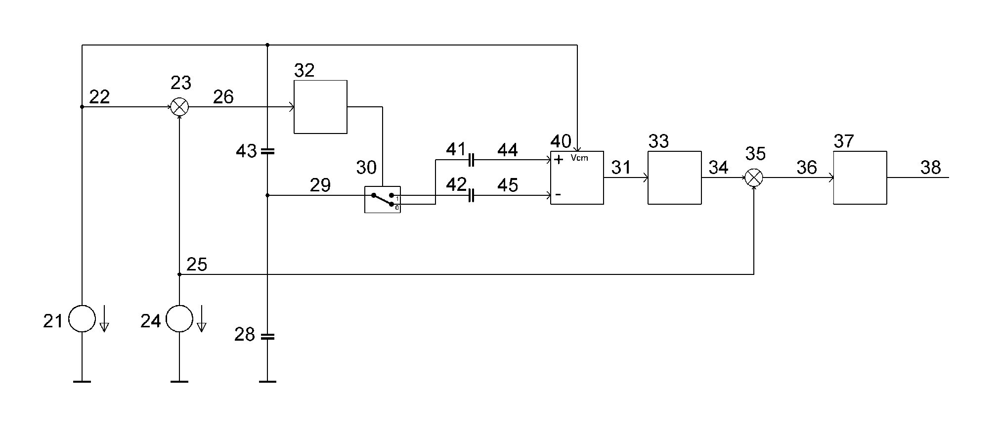
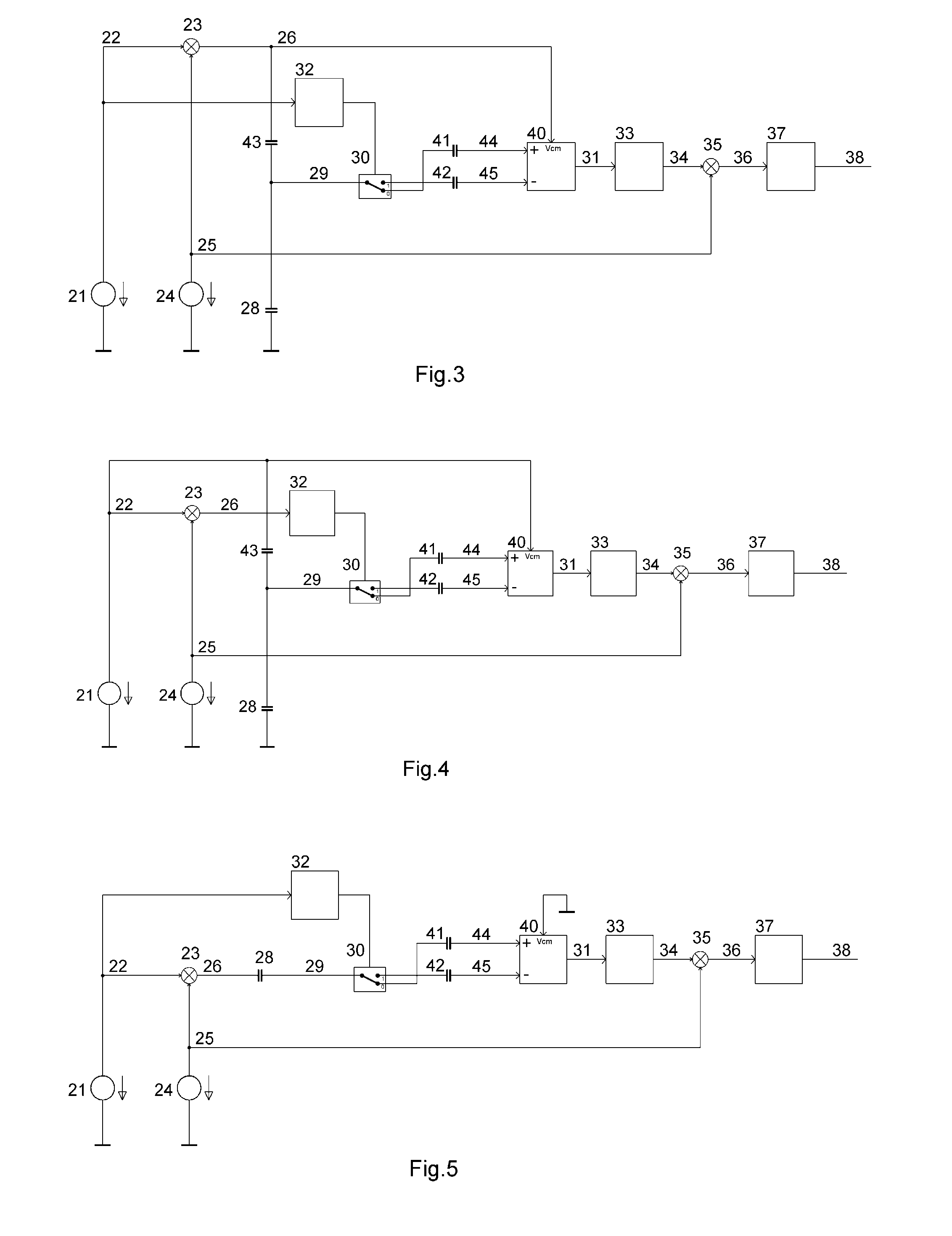
[0033]The circuit shown in FIG. 3 is a first embodiment allowing to substantially improve the immunity of the capacitance measurement circuit against injection of external parasitic AC currents. The capacitive measurement circuit is working in the so-called loading mode.

[0034]AC voltage source 21 generates an AC voltage signal of known frequency and amplitude, for example a periodic sine wave of 100 kHz and 1 V peak amplitude. Its output node 22 is connected to the input of adjustable phase shifter 32, and a first input of mixer 23. A second AC voltage source 24 generates a second AC voltage signal of know frequency and amplitude, but of lower frequency than the output frequency of AC voltage source 21, for example a periodic square wave of 1 kHz and 1V peak amplitude.

[0035]The output 25 of AC voltage source 24 is connected to the second input, the local oscillator input, of mixer 23. Mixer 23 multiplies the signals at its two inputs. For the specific example signals described above...


PUM


Abstract

A capacitive sensing circuit is disclosed, wherein the mixer is directly connected to the sense electrode. The AC transimpedance amplifier in front of the mixer in prior art is removed and replaced by a differential DC transimpedance amplifier respectively integrator. The mixer DC offset voltage or current together with the large amplification factor required after the mixer now would result in an inacceptable DC offset at the output of the signal chain. In order to eliminate the effect of the mixer offset, the amplifying stages after the mixer are AC coupled to the mixer output and one of the signals entering the mixer is phase modulated or amplitude modulated with a known low frequency signal. An additional mixer after the AC coupled amplifying stages is driven with the same low frequency modulating signal, resulting in the wanted DC output signal responsive to the capacitance to be measured.

Description

FIELD OF THE INVENTION[0001]The present invention generally relates to the technical field of capacitive measurement circuits and more specifically to a capacitive measurement system having one or more electrodes, in which the characteristics of a conductive body such as shape and location are determined by means of capacitive coupling via the electrically conductive body.BACKGROUND OF THE INVENTION[0002]Capacitive measurement and / or detection systems have a wide range of applications, and are among others widely used for the detection of the presence and / or the position of conductive body in the vicinity of an electrode of the system. A capacitive sensor, called by some electric field sensor or proximity sensor, designates a sensor, which generates a signal responsive to the influence of what is being sensed (a person, a part of a person's body, a pet, an object, etc.) upon an electric field. A capacitive sensor generally comprises at least one antenna electrode, to which is applie...

Claims


Application Information

Patent Timeline
Patent Type & Authority Applications(United States)
IPC IPC(8): G01R27/26
CPCH03K17/955H03K2217/960705G01R27/2605H03K2217/960775H03K2217/96077
Inventor LAMESCH, LAURENT
Owner IEE INT ELECTRONICS & ENG SA
Why Eureka
Try Eureka