Wireless electric field power transmission system and method

a technology of electric field and power transmission system, which is applied in the direction of electric energy management, inductance, electric devices, etc., can solve the problems of inefficient radiative energy transfer, inefficient energy transfer may be acceptable for data transmission, and the vast majority of power is radiated, so as to prevent electromagnetic field leakage and increase the electric field strength

Active Publication Date: 2013-06-13
SOLACE POWER INC
View PDF70 Cites 99 Cited by
  • Summary
  • Abstract
  • Description
  • Claims
  • Application Information

AI Technical Summary

Benefits of technology

[0027]In another embodiment, there is provided a container comprising the transmitter of the present aspect. The container may be shielded to prevent electromagnetic field (EMF) leakage. Electric field strength may be increased when the container is closed.

Problems solved by technology

As will be appreciated, this type of radiative energy transfer is inefficient because only a small portion of the supplied or radiated power, namely, that portion in the direction of, and overlapping with, the receiver is picked up.
The vast majority of the power is radiated in other directions and lost in free space.
Such inefficient energy transfer may be acceptable for data transmission, but is not practical when trying to transfer useful amounts of electrical energy for the purpose of doing work, such as for example, powering or charging electrical devices.
However, these directed radiation schemes typically require an uninterruptible line-of-sight between the transmitter and receiver as well as potentially complicated tracking and steering mechanisms in the case of mobile transmitters and / or receivers.
In addition, such directed radiation schemes may pose hazards to objects or people that cross or intersect the beam of radiated energy when modest to high amounts of power are being transmitted.
A device is composed of energy production and consumption devices situated a short distance apart, and it uses neither the propagation of electromagnetic waves nor induction and cannot be reduced to a simple arrangement of electrical capacitors.

Method used


Image

  • Wireless electric field power transmission system and method
  • Wireless electric field power transmission system and method
  • Wireless electric field power transmission system and method

Examples


Embodiment Construction

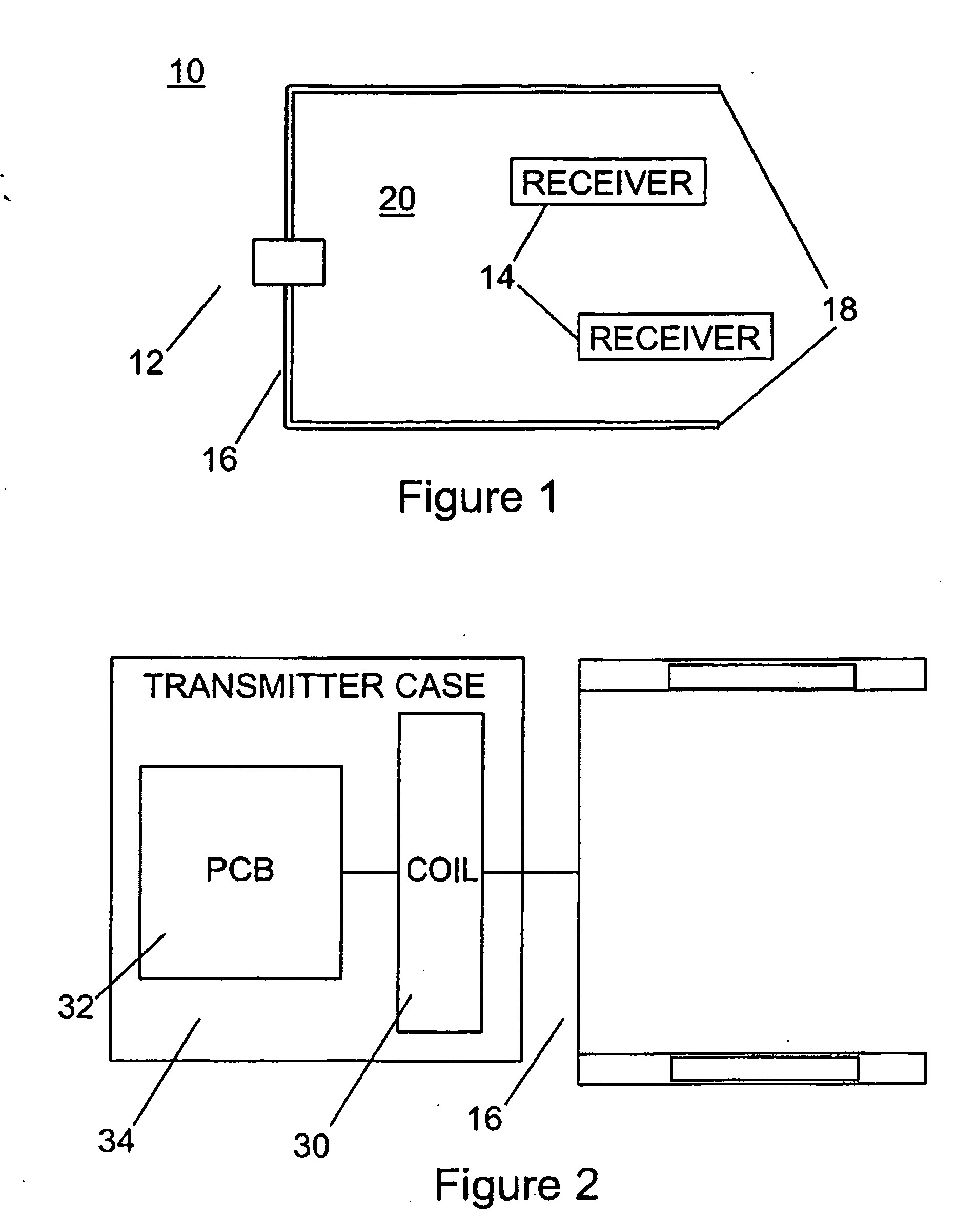
[0081]Turning now to FIG. 1, a wireless electric field power transmission system is shown and is generally identified by reference numeral 10. As can be seen, power transmission system 10 comprises a transmitter 12 comprising a transmitter antenna 16 coupled and a plurality of receivers 14. Although only two receivers 14 are shown, it will be appreciated that this is for ease of illustration only. The power transmission system 10 may comprise more or fewer receivers 14. The transmitter antenna 16 comprises two approximately parallel, laterally spaced conductors 18 defining a volume 20 between them. The conductors 18 are elongate and generally rectangular and are oriented such that major surfaces of the conductors face one another. In this embodiment, each conductor 18 is formed of aluminum foil tape due to its flexibility, low cost and availability. Each receiver 14 can be positioned within the volume 20 to harvest power wirelessly as a result of an electric field generated within t...


PUM


Abstract

A wireless electric field power transmission system comprises: a transmitter comprising a transmitter antenna, the transmitter antenna comprising at least two conductors defining a volume therebetween; and at least one receiver, wherein the transmitter antenna transfers power wirelessly via electric field coupling when the at least one receiver is within the volume.

Description

CROSS REFERENCE TO RELATED APPLICATIONS[0001]This application claims the benefit of U.S. Provisional Application No. 61 / 532,092 filed Sep. 7, 2011, the content of which is incorporated by reference in its entirety.FIELD OF THE INVENTION[0002]The present invention relates generally to wireless power transmission and in particular, to a wireless electric field power transmission system and method.BACKGROUND OF THE INVENTION[0003]A variety of radiative, or far-field, and non-radiative, or near-field, energy or power transfer techniques are known. For example, radiative wireless information transfer using low-directionality antennas, such as those used in radio and cellular communications systems and home computer networks, may be considered wireless energy transfer. As will be appreciated, this type of radiative energy transfer is inefficient because only a small portion of the supplied or radiated power, namely, that portion in the direction of, and overlapping with, the receiver is p...

Claims


Application Information

Patent Timeline
Patent Type & Authority Applications(United States)
IPC IPC(8): H02J17/00H02J7/00
CPCH03F1/56Y02T90/121H03F3/245H03F3/305H03F2200/09H03F2200/102H03F2200/387H03F2200/462H03F2203/30031H03F2203/30111H03F2203/30114H02J7/0042H02J17/00H02J7/025B60L11/182B60L11/1833B60L2210/10B60L2210/30B60L2210/40Y02T10/7005Y02T10/7241Y02T90/125Y02T90/12Y02T10/7216Y02T90/14Y02T90/127Y02T90/122H03L7/0812H03J2200/06H01Q1/2225H01Q1/273H01Q1/3216H01Q7/08H03F3/195H04B5/0037H04B5/0081Y02T10/7072B60L53/36H02J50/05H02J50/12H02J50/23H02J50/27H02J50/40H02J50/90H02J50/60H02J50/001H02J7/00034H02J50/005B60L53/122Y02T10/72Y02T10/70H02J50/70H02J7/0044H02J50/80B60L53/12Y02T10/90
Inventor POLU, NAGESHALAM, MD. JAHANGIRISLAM, SHEIKH MOMINULSOLTANI, NIMA
Owner SOLACE POWER INC
Why Eureka
Try Eureka