
Lens, backlight assembly and display apparatus having the same

a backlight assembly and display apparatus technology, applied in the field of lenses, can solve the problems of greatly increasing the manufacturing cost of the lcd display apparatus, and achieve the effects of/or the display apparatus including the backlight assembly, reducing the risk of irregular light distribution, and reducing the overall manufacturing cost of the backlight assembly

Active Publication Date: 2013-06-13
SAMSUNG DISPLAY CO LTD
View PDF9 Cites 15 Cited by
  • Summary
  • Abstract
  • Description
  • Claims
  • Application Information

AI Technical Summary

Benefits of technology

The invention aims to provide a more uniform and widely distributed lighting system using a lens that requires fewer light sources. Additionally, the invention reduces the use of a printed circuit board substrate, saving manufacturing costs and preventing uneven lighting. A dot pattern on a diffusion plate is used to disperse light more evenly, reducing bright spots and dark spots caused by uneven lighting.

Problems solved by technology

However, the point light source of the LED lamp has a small light distribution area for each point light source and a limited brightness.
Thus, the manufacturing cost of the LCD display apparatus is greatly increased.

Method used


Image

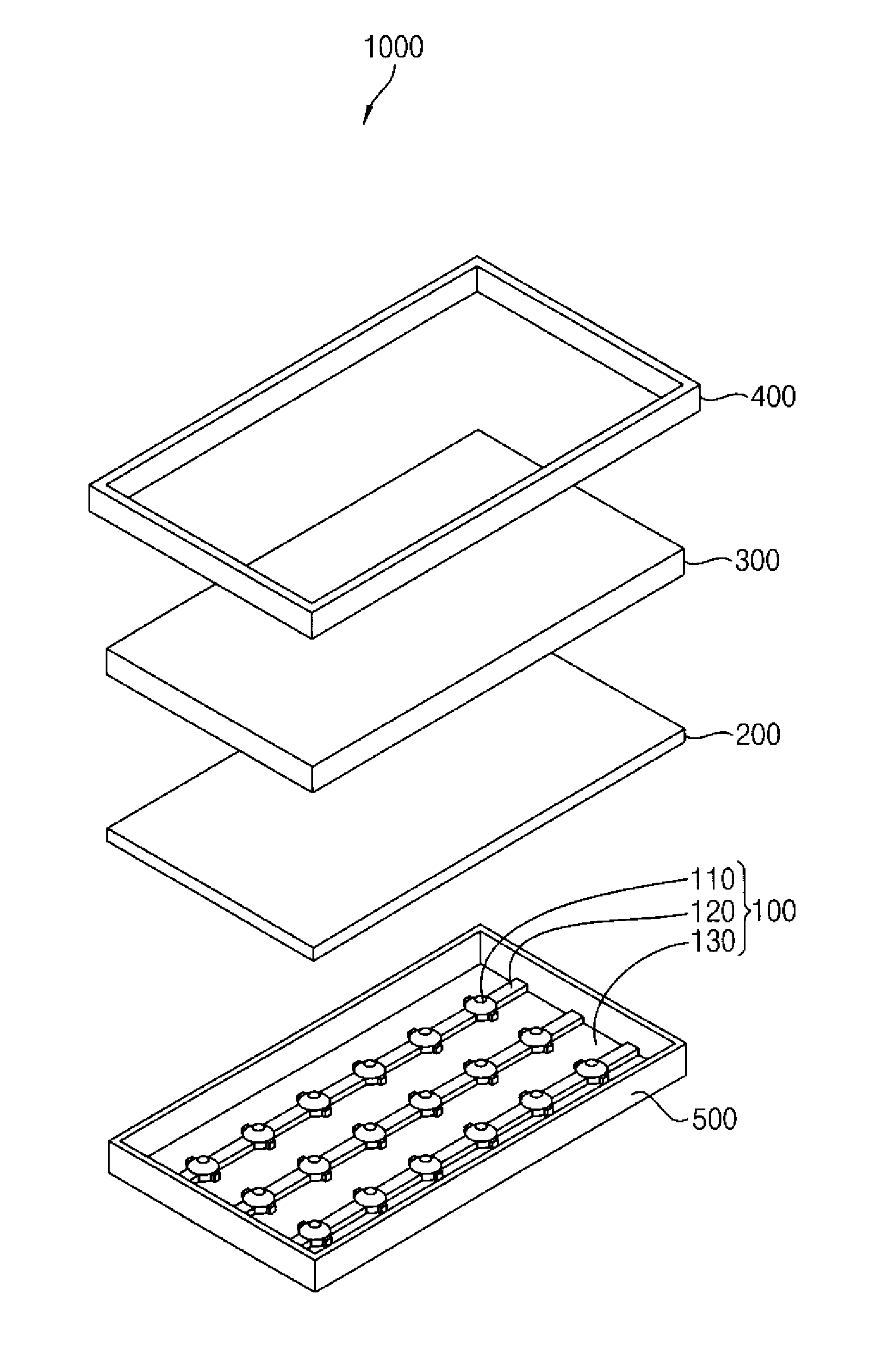
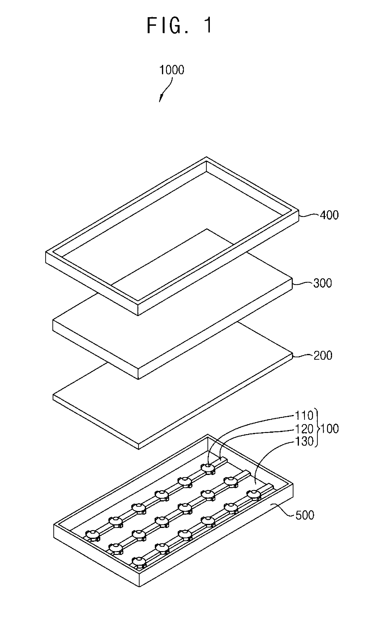
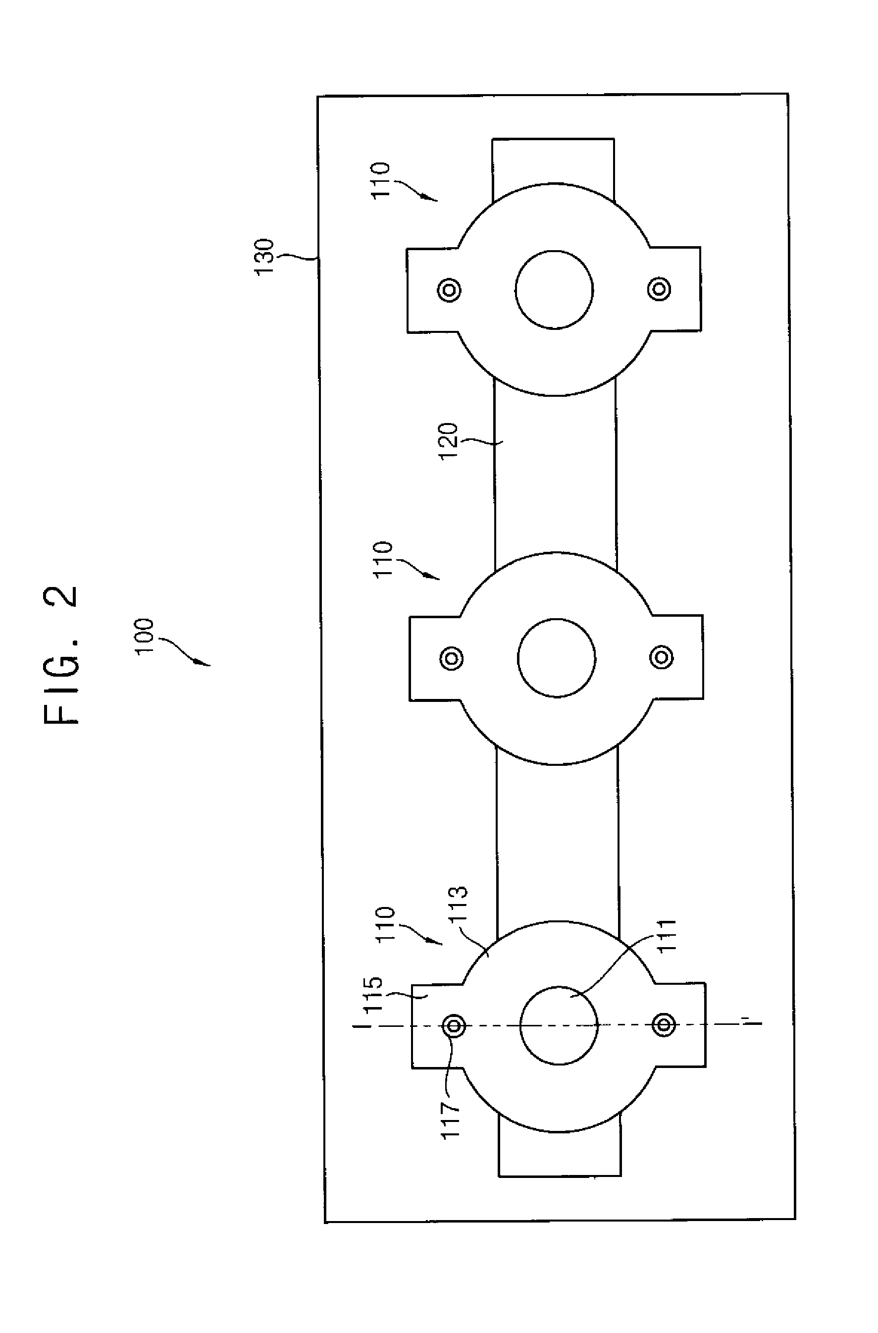
  • Lens, backlight assembly and display apparatus having the same
  • Lens, backlight assembly and display apparatus having the same
  • Lens, backlight assembly and display apparatus having the same

Examples


Embodiment Construction

[0046]It will be understood that when an element or layer is referred to as being “on,”“connected to” or “coupled to” another element or layer, the element or layer can be directly on, connected or coupled to another element or layer or intervening elements or layers. In contrast, when an element is referred to as being “directly on,”“directly connected to” or “directly coupled to” another element or layer, there are no intervening elements or layers present. As used herein, connected may refer to elements being physically and / or electrically connected to each other. Like numbers refer to like elements throughout. As used herein, the term “and / or” includes any and all combinations of one or more of the associated listed items.

[0047]It will be understood that, although the terms first, second, third, etc., may be used herein to describe various elements, components, regions, layers and / or sections, these elements, components, regions, layers and / or sections should not be limited by t...


PUM

PropertyMeasurementUnit
angleaaaaaaaaaa
roughnessaaaaaaaaaa
orientation angle distributionaaaaaaaaaa

Abstract

A lens includes an upper flat surface having a first outer diameter, a bottom surface having a second outer diameter and a third inner diameter, an external curved surface which connects the upper flat surface and the bottom surface, and an inner curved surface which protrudes toward the upper flat surface from the bottom surface at the third inner diameter.

Description

[0001]This application claims priority to Korean Patent Application No. 10-2011-0132850, filed on Dec. 12, 2011, and all the benefits accruing therefrom under 35 U.S.C. §119, the contents of which are herein incorporated by reference in its entirety.BACKGROUND OF THE INVENTION[0002]1. Field of the Invention[0003]Exemplary embodiments of the invention relate to a lens, a backlight assembly and a display apparatus having the lens. More particularly, exemplary embodiments of the invention relate to a lens, a backlight assembly and a display apparatus having the lens, with respect to fewer light sources.[0004]2. Description of the Related Art[0005]A liquid crystal display (“LCD”) apparatus needs an external light source for displaying an image with desirable brightness since the LCD apparatus cannot generate light by itself The LCD apparatus includes a backlight assembly as the external light source, and a LCD display panel which displays the image using light from the external light so...

Claims


Application Information

Patent Timeline
Patent Type & Authority Applications(United States)
IPC IPC(8): G02F1/13357G09F13/04F21V5/04
CPCF21V5/046G02F1/133603G02B19/0061G02B19/0009G02B5/0263G02F2001/133607G02F1/133607G02B3/00G02F1/1333G02F1/1335
Inventor HA, JU-HWAKIM, JOONG-HYUNSEO, JINSON, JU-YOUNYEO, DONG-MINYE, SANG-HEONLEE, YOUNG-KEUNLEE, JI-WON
Owner SAMSUNG DISPLAY CO LTD
Learn More