Electrophotographic member, intermediate transfer member, image forming apparatus, and method for manufacturing electrophotographic member

a technology of electrophotography and transfer member, applied in the direction of electrographic process, instruments, transportation and packaging, etc., can solve the problem of degrading the image quality of the transferred image, and achieve the effect of enhancing the transfer efficiency

Active Publication Date: 2013-06-13
CANON KK
View PDF1 Cites 26 Cited by
  • Summary
  • Abstract
  • Description
  • Claims
  • Application Information

AI Technical Summary

Benefits of technology

[0006]As has been described above, a method of coating a fluorine compound on the surface layer of an intermediate transfer member is proposed for the purpose of enhancing transfer efficiency, but it has been found that even such an intermediate transfer member occasionally causes the degradation of image quality of a transferred image in a process of transferring the image onto a transfer material from the intermediate transfer member, which originates in the deterioration of the surface layer of the intermediate transfer member, when the intermediate transfer member has repeatedly output images. As a result of having investigated a mechanism by which such a phenomenon occurs, it has been considered as the reason that the surface of the intermediate transfer member chemically deteriorates by an electric discharge in the transfer process, and physically deteriorates by an abrasion or the like of the surface layer in a cleaning process.
[0007]The development of an intermediate transfer member having such high durability is desired as to be capable of keeping a high transfer efficiency of the surface layer of the intermediate transfer member even when the image forming apparatus has thus repeatedly printed images. Particularly, it is desired for an image forming apparatus which prints images at a high speed to have properties of excellently keeping a transfer performance when thus printing a large number of images.
[0008]An object of the present invention is to provide an electrophotographic member which enhances the durability, and can keep the transfer characteristics even when having repeatedly output images.

Problems solved by technology

As has been described above, a method of coating a fluorine compound on the surface layer of an intermediate transfer member is proposed for the purpose of enhancing transfer efficiency, but it has been found that even such an intermediate transfer member occasionally causes the degradation of image quality of a transferred image in a process of transferring the image onto a transfer material from the intermediate transfer member, which originates in the deterioration of the surface layer of the intermediate transfer member, when the intermediate transfer member has repeatedly output images.

Method used


Image

  • Electrophotographic member, intermediate transfer member, image forming apparatus, and method for manufacturing electrophotographic member
  • Electrophotographic member, intermediate transfer member, image forming apparatus, and method for manufacturing electrophotographic member
  • Electrophotographic member, intermediate transfer member, image forming apparatus, and method for manufacturing electrophotographic member

Examples


example 1

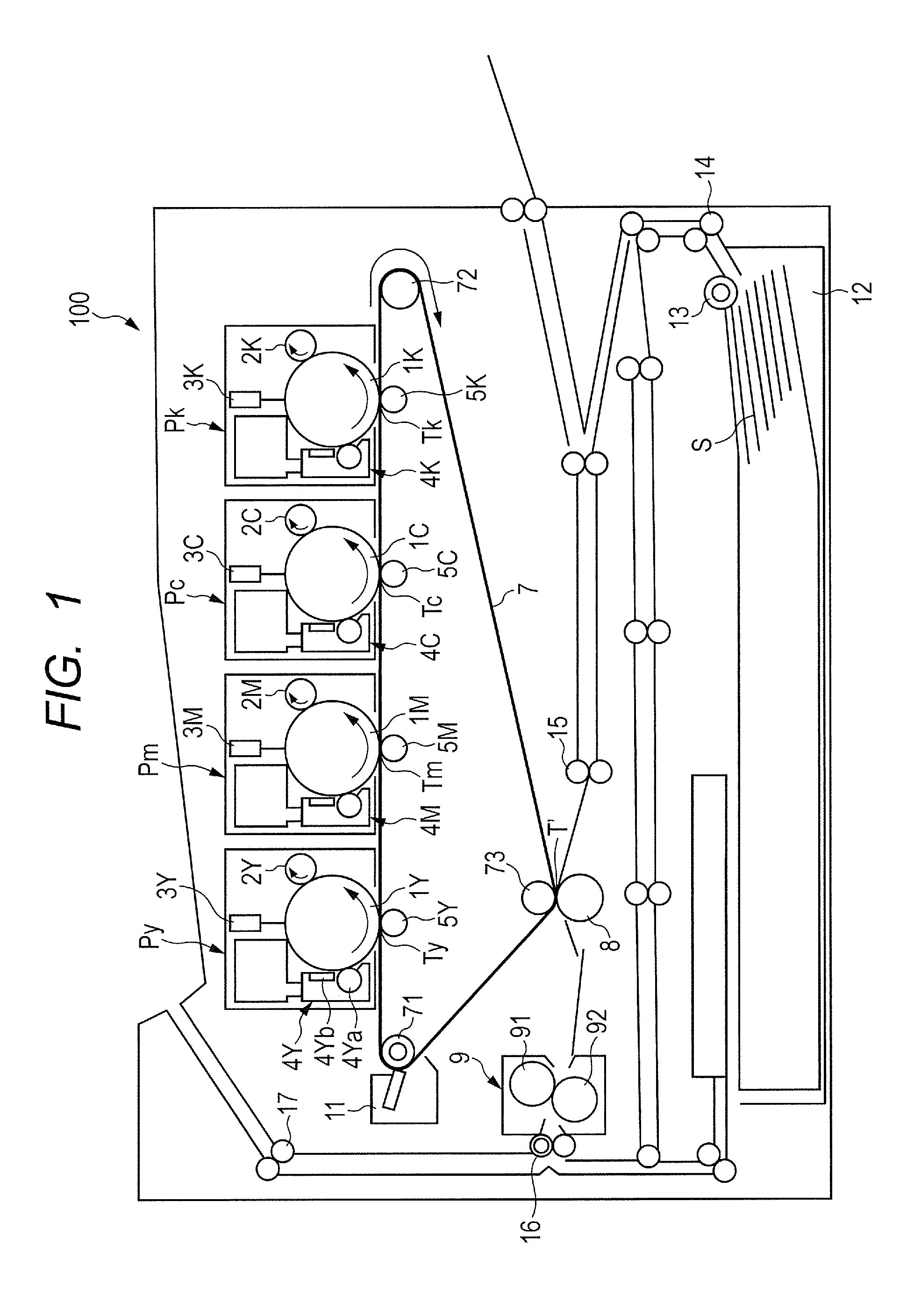
[0085]An electrophotographic member of the present invention was produced by using an intermediate transfer belt made from polyimide, which was equipped in iRC2620 made by Canon Inc. as a base layer, and forming a surface layer by applying a dispersion liquid shown below onto this base layer with a ring coat method. For information, Table 1 shows volume resistance values, surface resistance values and evaluation results of respective intermediate transfer belts of Examples 1-1 to 1-7 and Comparative Examples 1-1 to 1-3, and Table 2 shows volume resistance values, surface resistance values and evaluation results of respective intermediate transfer belts of Examples 1-8 and 1-9, and Comparative Examples 1-4 to 1-6. Incidentally, any of the volume resistance values and the surface resistance values of the intermediate transfer belts which were produced in the Examples was measured with Hiresta made by Mitsubishi Chemical Corporation.

example 1-1

[0086]Dipentaerythritol hexaacrylate: 8 parts by mass

Pentaerythritol tetraacrylate: 17 parts by mass

Pentaerythritol triacrylate: 5 parts by mass

Methyl ethyl ketone: 43 parts by mass

Ethylene glycol: 15 parts by mass

Antimony-doped tin-oxide fine particle (ISHIHARA SANGYO KAISHA, LTD. SN series): 4 parts by mass

Photopolymerization initiator (IRGACURE 184): 2 parts by mass

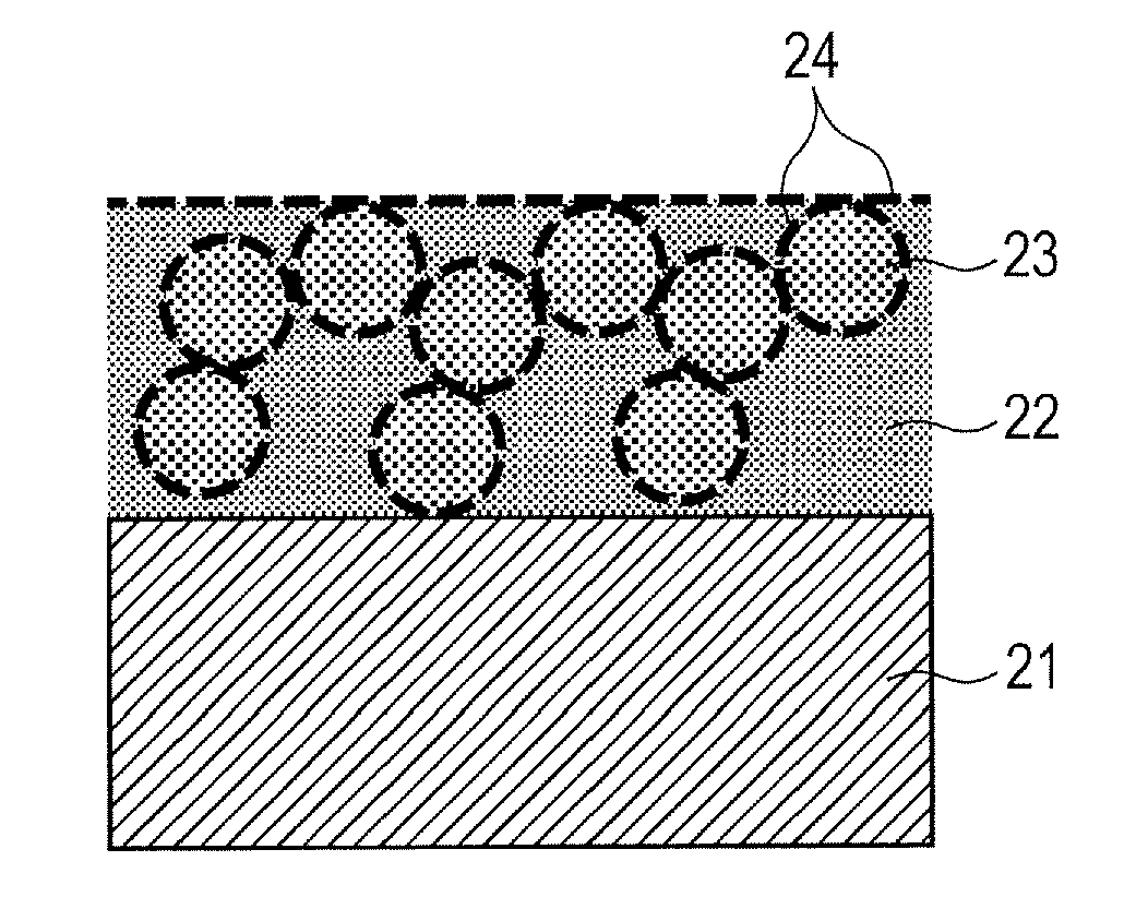
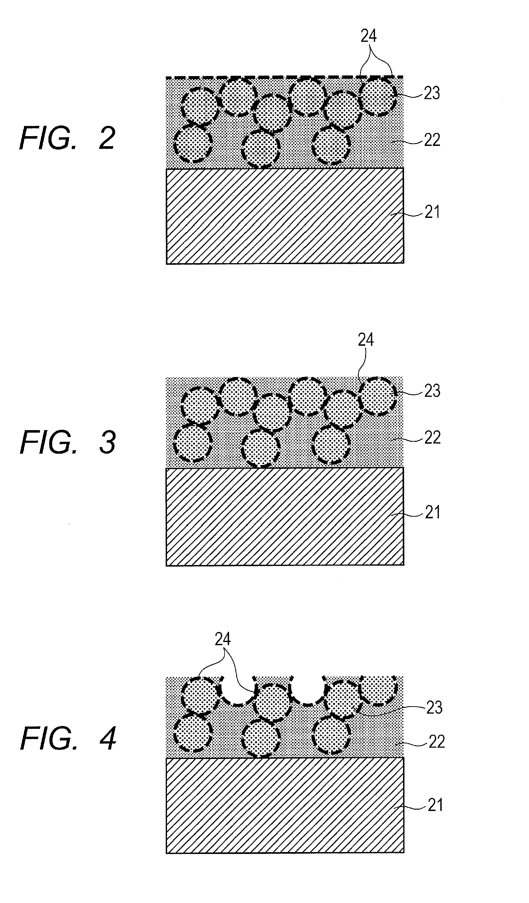
Tetrafluoroethylene fine particle

(LUBRON L-2 made by DAIKIN INDUSTRIES, LTD, with average diameter of primary particles of approximately 0.3 μm): 15 parts by mass

Fluorocarbon resin dispersing agent (GF-300 made by Toagosei Co., Ltd.): 1 part by mass

PFPE (MD500 made by Solvay Solexis S.p.A.): 0.4 parts by mass

[0087]These compounds were mixed and dispersed by a stirring type homogenizer, and then were dispersed by a dispersion device Nanomizer (made by YOSHIDA KIKAI CO., LTD.) to form a mixture dispersion liquid. The mixture dispersion liquid was coated onto the above described base layer made from polyimide, the coated ...

example 1-2

[0090]An intermediate transfer belt 1-2 was obtained by being produced in a similar way to that of Example 1-1 except that dipentaerythritol hexaacrylate was not used, the amount of pentaerythritol tetraacrylate was changed to 27 parts by mass from 17 parts by mass, and the amount of pentaerythritol triacrylate was changed to 3 parts by mass from 5 parts by mass, in Example 1-1.

[0091]In addition, images were evaluated in a similar way to that in Example 1 by using the intermediate transfer belt 1-2 instead of using the intermediate transfer belt 1-1. The evaluation results are shown in Table 1.


PUM

PropertyMeasurementUnit
contact angleaaaaaaaaaa
volume resistivityaaaaaaaaaa

Abstract

An object of the present invention is to provide: an electrophotographic member which enhances image quality, prevents the lowering of a grade of an image even when images have been repeatedly output, and can remarkably enhance the stability of the grade of the image; an intermediate transfer member; and an image forming apparatus. The electrophotographic member includes a base layer and a surface layer, wherein the surface layer has a binder resin, perfluoropolymer fine particles, a fluorocarbon resin dispersing agent and a particular fluorine compound, wherein the perfluoropolymer fine particle has a fluorine compound carried on its surface.

Description

BACKGROUND OF THE INVENTION[0001]1. Field of the Invention[0002]The present invention relates to an electrophotographic member which can be used for an electrophotographic type of an image forming apparatus such as a copying machine and a printer, an intermediate transfer member, an image forming apparatus using the electrophotographic member, and a method for manufacturing the electrophotographic member.[0003]2. Description of the Related Art[0004]In recent years, in an electrophotographic type of an image forming apparatus such as a copying machine and a printer, an image forming apparatus has been marketed which can obtain a color image of high quality. Generally, when obtaining the color image of the high quality, firstly, the image forming apparatus develops a toner image of each color by each color, then sequentially transfers the developed image onto an intermediate transfer member, and forms the color image on the intermediate transfer member. Next, the image forming apparat...

Claims


Application Information

Patent Timeline
Patent Type & Authority Applications(United States)
IPC IPC(8): B32B9/04B05D3/02B32B5/16G03G15/01C23F1/00
CPCG03G15/162G03G2215/0129G03G5/14G03G5/14726Y10T428/254B05D3/068B05D3/12B05D3/107B05D3/02G03G2215/1695Y10T428/3154Y10T428/31544Y10T428/31504Y10T428/31935
Inventor SATO, KOICHIKAMEYAMA, NAOTOONUMA, KENJINAKAMURA, KOICHIYOSHIKAWA, TADANOBUTOMINAGA, HIROSHIWATANABE, AKIRASHIMIZU, YASUSHISAKAMOTO, RIEKO
Owner CANON KK
Why Eureka
Try Eureka