Solar receiver absorber and solar receiver comprising at least one such absorber

a solar receiver and absorber technology, applied in the field of solar receiver absorbers, can solve the problems of significant temperature difference between the illuminated face and the solar receiver, high operating temperature, and harsh conditions of the solar receiver

Inactive Publication Date: 2013-06-20
COMMISSARIAT A LENERGIE ATOMIQUE ET AUX ENERGIES ALTERNATIVES +1
View PDF1 Cites 17 Cited by
  • Summary
  • Abstract
  • Description
  • Claims
  • Application Information

AI Technical Summary

Problems solved by technology

The solar receiver is subject to very harsh conditions.
Indeed, it is subject to a high operating temperature, thermal gradients through the inner structure thereof associated with the conductive transfer of a high heat flux, and rapid wide-ranging temperature variations, particularly during cloudy spells.
But, in the case of gas, such as water vapour or air, the exchange coefficient at the panel drops, the lighting on one face of the tubes by the high solar flux gives rise to a significant difference in temperature between the illuminated face and the rear face, hence deformations suitable for resulting in tube rupture.
This type of receiver offers a high transfer efficiency; however, the design thereof is complex and it is expensive and has not been tested in large-scale industrial applications.

Method used


Image

  • Solar receiver absorber and solar receiver comprising at least one such absorber
  • Solar receiver absorber and solar receiver comprising at least one such absorber
  • Solar receiver absorber and solar receiver comprising at least one such absorber

Examples


first embodiment

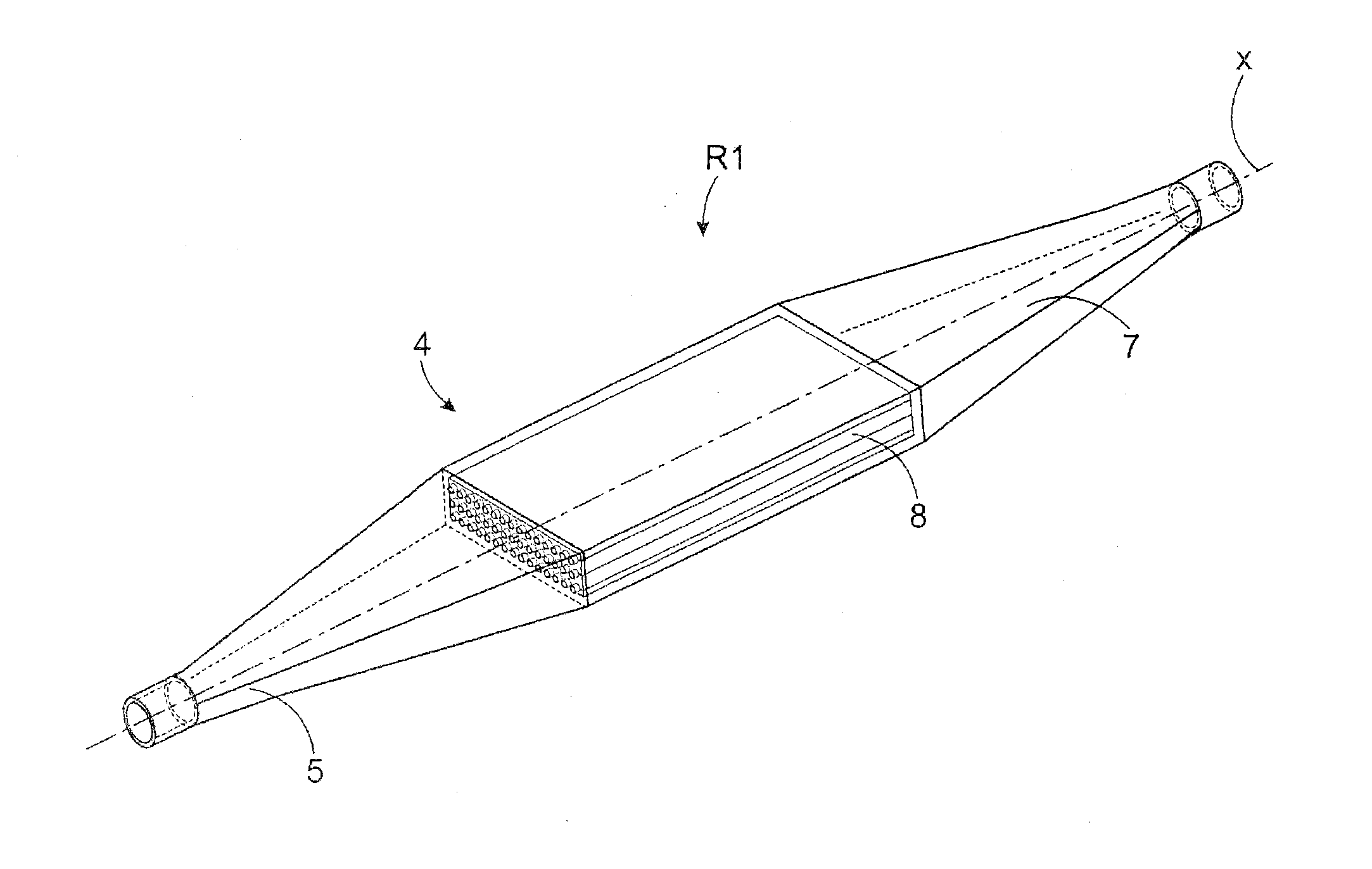
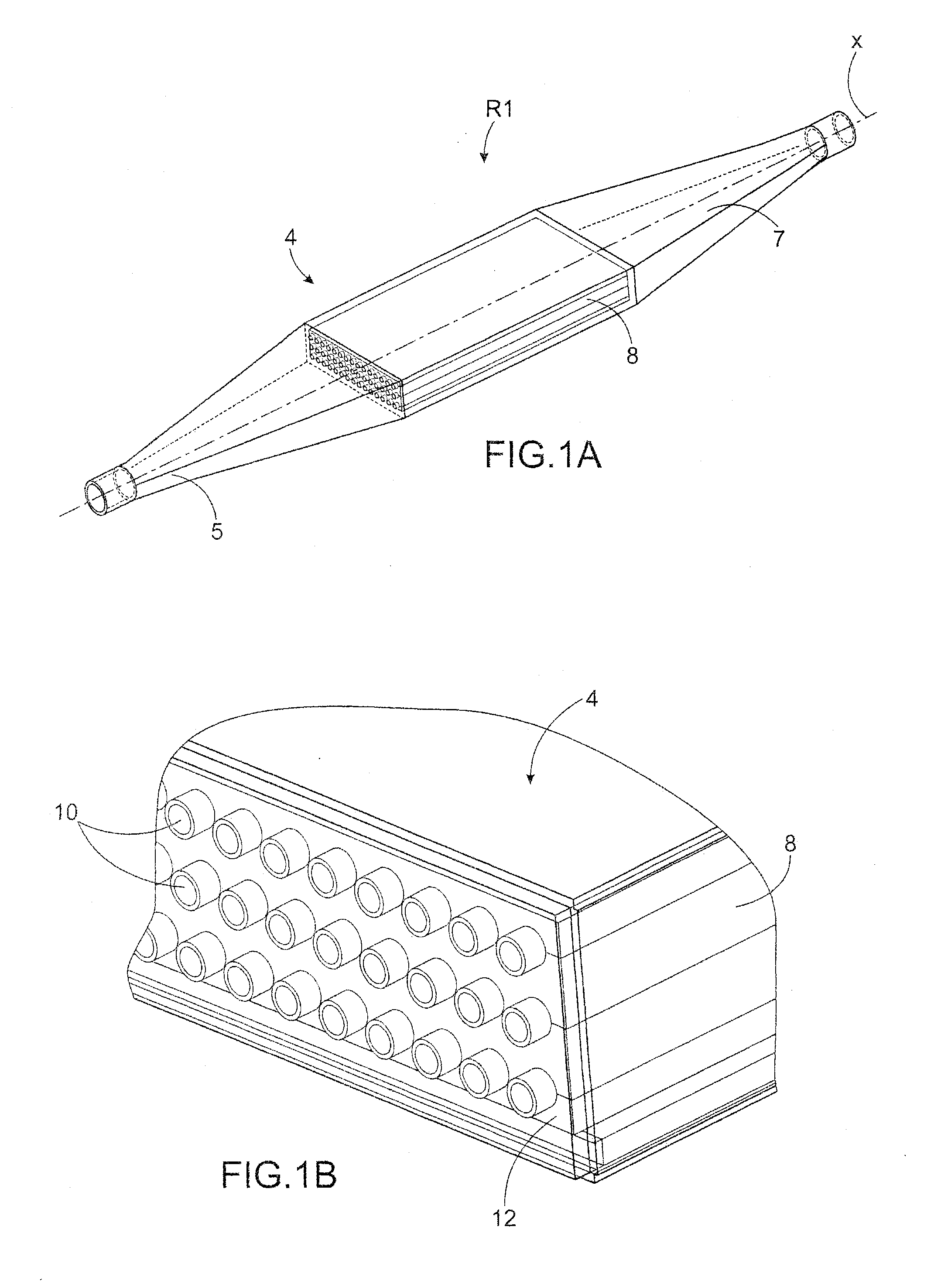
[0028]FIG. 1A is a perspective view of a receiver according to the invention

[0029]FIG. 1B is a detailed view of FIG. 1A,

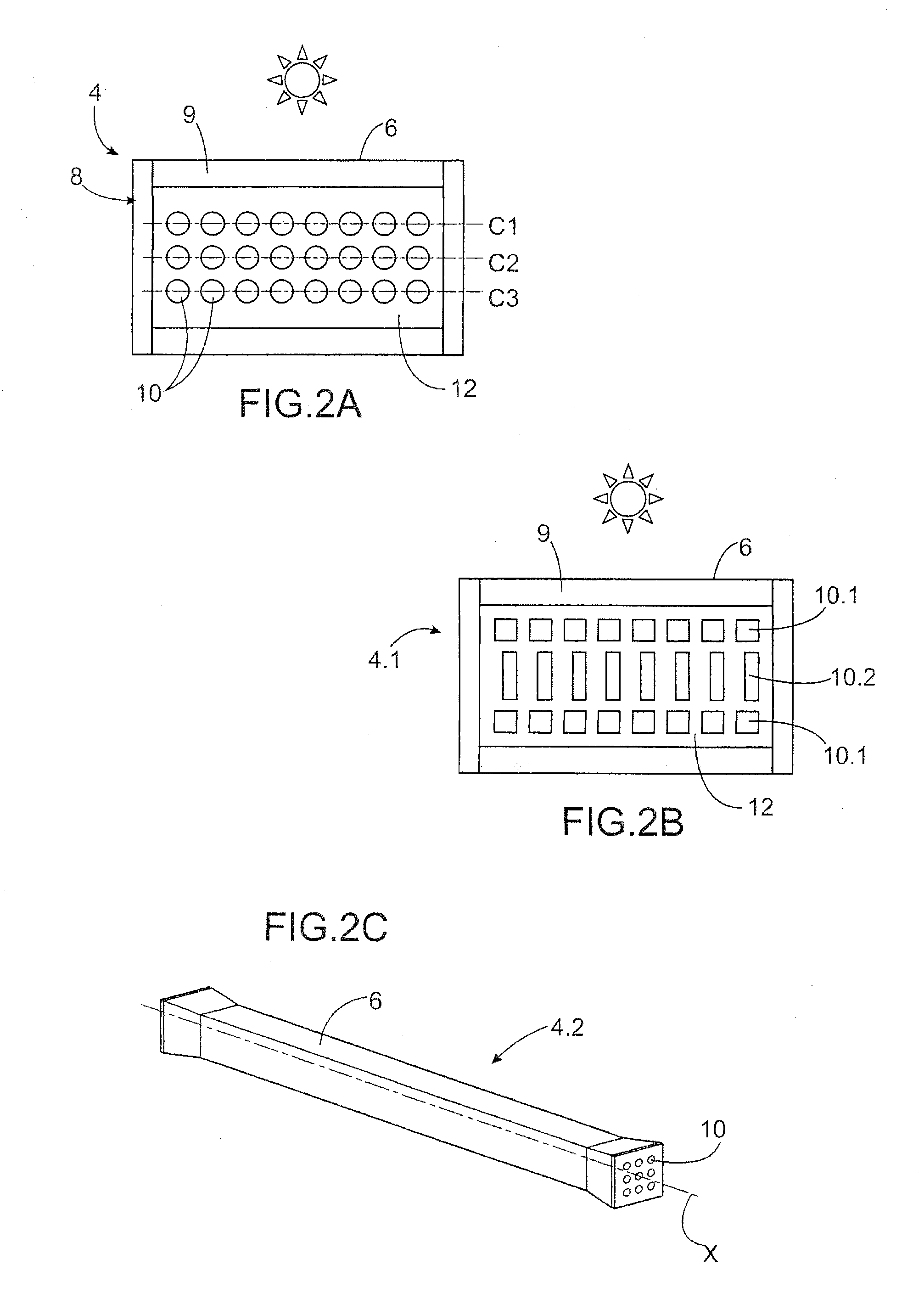
[0030]FIG. 2A is a cross-section view of an example of an embodiment of a solar receiver absorber according to the present invention,

[0031]FIG. 2B is a cross-section view of an alternative embodiment in FIG. 2A,

[0032]FIG. 2C is a perspective view of an absorber according to the present invention comprising three layers of three tubes,

[0033]FIG. 2D is a perspective view of a further alternative embodiment of an absorber according to the present invention,

[0034]FIG. 3 is a cross-section view of a further example of an embodiment of an absorber according to the present invention comprising an additional heat storage area,

[0035]FIGS. 4A and 4B are cross-section views of alternative embodiments of an absorber according to the present invention using phase-change materials,

[0036]FIG. 5A is a side view of an absorber according to the present invention during the assembly ...

second embodiment

[0042]FIG. 9 is a schematic representation of a receiver according to the present invention superimposed with the solar flux map,

[0043]FIG. 10 is a schematic representation of a further example of a receiver according to the second embodiment,

[0044]FIGS. 11A and 11B are schematic perspective views of the front face and rear face, respectively of a practical embodiment of the receiver in FIG. 10,

[0045]FIGS. 12, 13 and 14 are schematic representations of various connection modes between absorbers of a receiver according to the second embodiment,

[0046]FIG. 15 is a schematic representation of a further example of a modular receiver according to the second embodiment,

[0047]FIG. 16 is a graphic representation of the progression of the temperature in ° C. of the fluid and of the absorber panel to be illuminated if the cold fluid supplies the absorbers situated in a high-flux area, and the absorbers situated in a low-flux area are supplied with the fluid outflowing from the absorbers situat...


PUM

PropertyMeasurementUnit
temperaturesaaaaaaaaaa
inlet temperatureaaaaaaaaaa
outer diameteraaaaaaaaaa

Abstract

A solar power tower solar receiver absorber including: an enclosure; at least one panel configured to be illuminated by solar flux; a core made of at least one material with heat conductivity at least partially encompassed by the enclosure; and a plurality of tubes passing through the core and extending substantially in a parallel direction with respect to the panel configured to be illuminated. The tube is configured for circulation of a fluid to be heated, for example a gas for operating a gas turbine.

Description

FIELD OF THE INVENTION AND STATE OF THE RELATED ART[0001]The present invention relates to a solar receiver absorber, a solar receiver comprising at least one such absorber and a concentrating solar power plant comprising at least one such receiver, more specifically a solar power tower.[0002]Concentrating solar thermal technology consists of using solar radiation to heat a heat transfer fluid acting as a heat source in a thermodynamic cycle. Concentration makes it possible to reach temperatures of varying levels and thus benefit from varying degrees of thermodynamic conversion efficiency.[0003]Typically, there are four categories of Concentrating Solar Power (CSP) systems: line-focus parabolic trough collectors, linear Fresnel concentrators, central receiver tower systems and mobile-focus parabolic receivers.[0004]A solar power tower particularly comprises a solar receiver receiving solar radiation transmitted by mirrors referred to as heliostats. The solar receiver is the site wher...

Claims


Application Information

Patent Timeline
Patent Type & Authority Applications(United States)
IPC IPC(8): F24J2/24F24J2/46F24S10/70F24S10/80F24S20/20F24S23/70F24S23/77
CPCF24J2/07F24J2/16F24J2/24F24J2/28F24J2/34F24J2/4641F24J2/4654Y02E10/41Y02E10/44F24J2/242F24J2/4652F24S10/70F24S10/80F24S20/20F24S23/77F24S60/10F24S70/30F24S80/10F24S10/72F24S80/45Y02E10/40
Inventor COUTURIER, RAPHAELFERRIERE, ALAINPRA, FRANCKTOCHON, PATRICEVIDOTTO, FABIEN
Owner COMMISSARIAT A LENERGIE ATOMIQUE ET AUX ENERGIES ALTERNATIVES
Why Eureka
Try Eureka