
Dechuck control method and plasma processing apparatus

a control method and plasma processing technology, applied in the direction of electrical apparatus, electrostatic holding devices, electric discharge tubes, etc., can solve the problems of residual electric charge not being discharged, processing objects may crack or be displaced, surface of electrostatic chuck change over tim

Active Publication Date: 2013-06-20
TOKYO ELECTRON LTD
View PDF13 Cites 37 Cited by
  • Summary
  • Abstract
  • Description
  • Claims
  • Application Information

AI Technical Summary

Benefits of technology

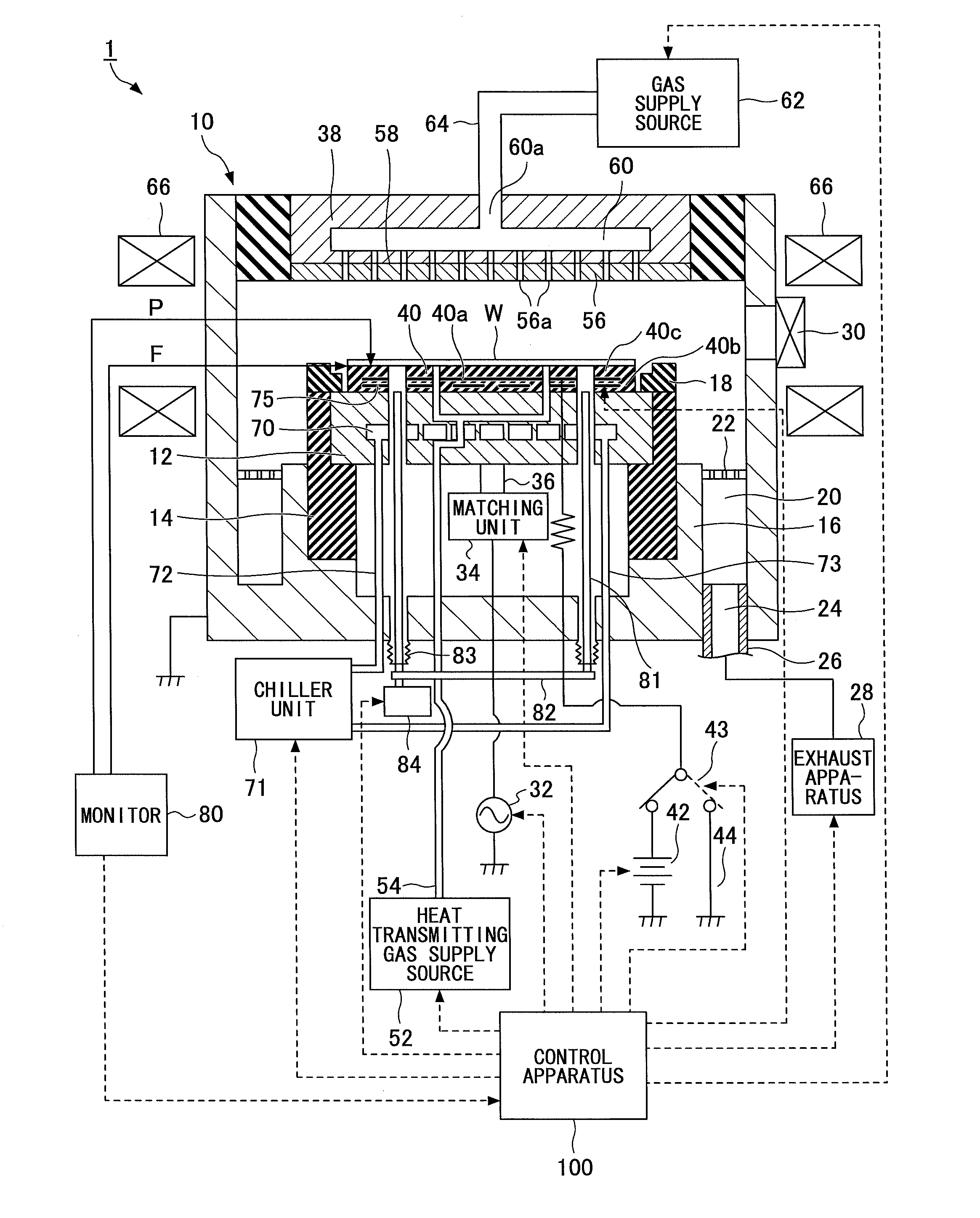
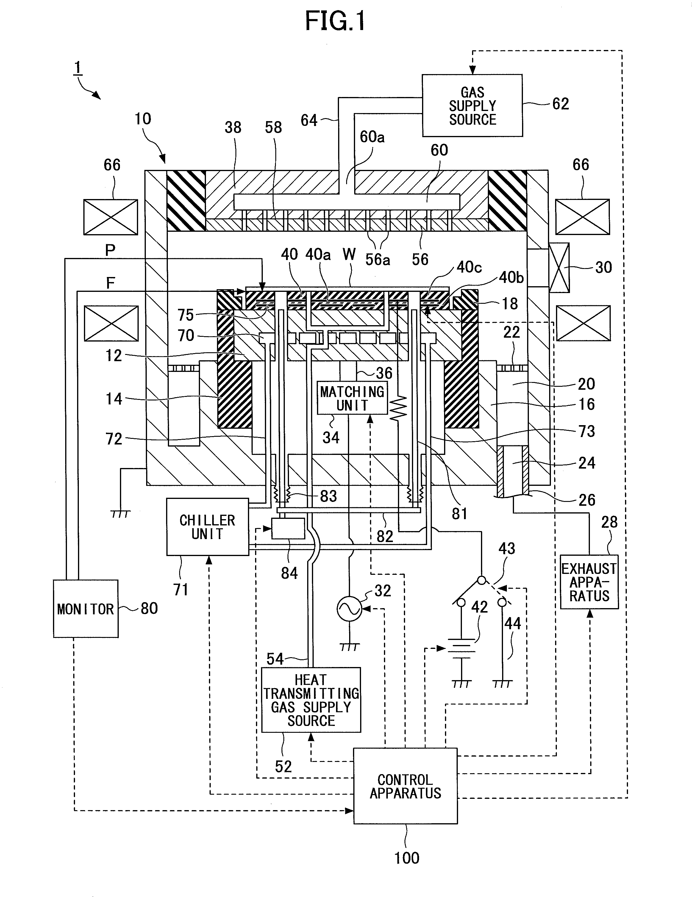
The present invention provides a dechuck control method for a plasma processing apparatus that overcomes the limitations and disadvantages of existing methods. The method includes steps of monitoring the pressure of a heat transmitting gas and the leakage flow rate of the gas from the processing object, applying a voltage to the chuck electrode to remove residual electric charge, and evacuating the inert gas from the processing chamber to reduce the pressure. The method also includes steps of detecting the pressure of the heat transmitting gas and stopping the dechucking process if the pressure exceeds a predetermined threshold. The invention provides a more efficient and effective dechuck control method that improves the processing object's dechucking process.

Problems solved by technology

However, the surface of the electrostatic chuck may change over time.
Such a residual electric charge cannot be discharged by the above discharge process.
As a result, the support pins may be raised while an electrostatic suction force created by the residual electric charge still remains on the surface of the electrostatic chuck so that the processing object may crack or be displaced, for example.
Although the discharge method disclosed in Patent Document 1 enables the cancelling of the electric charge generated at the rear face of the wafer, it cannot be used to discharge the residual electric charge remaining on the surface of the electrostatic chuck.
Thus, even if the discharge method of Patent Document 1 is implemented, it may be difficult to dechuck the processing object from the electrostatic chuck when a suction force is generated by the residual electric charge accumulated in the insulating film formed on the surface of the electrostatic chuck.

Method used


Image

  • Dechuck control method and plasma processing apparatus
  • Dechuck control method and plasma processing apparatus
  • Dechuck control method and plasma processing apparatus

Examples


first modification

[0137](First Modification)

[0138]In the dechuck control method according to the above modified embodiment, the He pressure of 2.6 Torr is determined to be the threshold value based on which a determination may be made as to whether the wafer W may be dechucked. FIG. 16 is a flowchart showing process steps for performing a suction monitoring process according to a first modified embodiment. The monitoring process of FIG. 16 is a modified embodiment of the suction monitoring process performed in step S110 of the dechuck control method shown in FIG. 7.

[0139]That is, the first modified embodiment of FIG. 16 relates to the suction monitoring process that is performed after the plasma process of steps S100-S106 and the discharge process of steps S107-S109 of FIG. 7.

[0140]The suction monitoring process according to the first modified embodiment is performed by the control unit 115. In FIG. 16, first, He gas is supplied to the rear face of the wafer W (S300). Then, after the pressure at the ...

second modification

[0151](Second Modification)

[0152]In the following, a suction monitoring process according to a second modified embodiment is described. FIG. 19 is a flowchart showing process steps for executing the suction monitoring process according to the second modified embodiment. The suction monitoring process of FIG. 19 is another modification of the suction monitoring process performed in step S110 of the dechuck control method of FIG. 7.

second modified embodiment

[0153]FIG. 19 differs from the first modified embodiment of FIG. 16 in that it includes step S310. That is, in the second modified embodiment, when the He pressure of the edge region detected one second after stopping the He gas supply is greater than the He pressure alarm threshold value 2.6 Torr, the control unit 115 does not immediately terminate the wafer W dechuck process but proceeds to step S310 where the control unit 115 determines whether the suction monitoring process steps (i.e., steps S300-S302) have been performed at least a predetermined number of times. If it is determined that the monitoring process steps have not been performed the predetermined number of times, the process goes back to step S300 so that the suction monitoring steps S300-S302 may be repeated. That is, the He gas is supplied again for six seconds after which the He gas supply is stopped and the pressure at the edge region of the wafer W rear face is detected one second after stopping the He gas suppl...


PUM

PropertyMeasurementUnit
Fractionaaaaaaaaaa
Timeaaaaaaaaaa
Pressureaaaaaaaaaa

Abstract

A dechuck control method includes performing a discharge process by introducing an inert gas into a processing chamber and maintaining the pressure within the processing chamber at a first pressure; monitoring the pressure of a heat transmitting gas supplied to the processing object rear face and / or the leakage flow rate of the heat transmitting gas; obtaining the amount and polarity of the residual electric charge of the electrostatic chuck surface and applying a voltage for supplying an electric charge that is of the same amount as the residual electric charge but of the opposite polarity to a chuck electrode; evacuating the inert gas from the processing chamber while applying the voltage to the chuck electrode and reducing the pressure within the processing chamber to a second pressure; and turning off the voltage applied to the electrostatic chuck and dechucking the processing object from the electrostatic chuck.

Description

CROSS-REFERENCE TO RELATED APPLICATIONS[0001]This patent application is based on and claims the benefit of priority of Japanese Patent Application No. 2011-278415 filed on Dec. 20, 2011; U.S. Patent Application No. 61 / 580,338 filed on Dec. 27, 2011; Japanese Patent Application No. 2012-182706 filed on Aug. 21, 2012; and U.S. Patent Application No. 61 / 696,462 filed on Sep. 4, 2012; the entire contents of which are incorporated herein by reference.BACKGROUND OF THE INVENTION[0002]1. Field of the Invention[0003]The present invention relates to a dechuck control method and a plasma processing apparatus.[0004]2. Description of the Related Art[0005]A plasma process is often performed in vacuum by evacuating gas from a processing chamber. In such a process, a processing object is placed on an electrostatic chuck (ESC) that is arranged on a stage of the processing chamber.[0006]The electrostatic chuck includes a conductive sheet-type chuck electrode that is arranged between dielectric membe...

Claims


Application Information

Patent Timeline
IPC IPC(8): H02N13/00C23F1/08
CPCH02N13/00H01J37/32715H01L21/6831C23F1/08
Inventor SENZAKI, SHIGERUMIKAMI, SHUNICHITOBANA, TOSHIKATSU
Owner TOKYO ELECTRON LTD
Learn More