Loosely-coupled radio antenna apparatus and methods

a loosely coupled, radio antenna technology, applied in the direction of simultaneous aerial operations, electrical apparatus, antenna supports/mountings, etc., can solve the problems of reducing antenna efficiency and bandwidth, adversely affecting the operation of internal radio frequency antennas, and high electrical losses, and achieve the effect of increasing the radiation efficiency of the multiband antenna apparatus

Active Publication Date: 2013-06-20
PULSE FINLAND
View PDF18 Cites 36 Cited by
  • Summary
  • Abstract
  • Description
  • Claims
  • Application Information

AI Technical Summary

Benefits of technology

[0015]In another variant, the grounding of the first end cap is configured to increase radiation efficiency of the multiband antenna apparatus.
[0019]In one variant, the grounding of the end cap is configured to increase radiation efficiency of the multiband antenna apparatus, and the second band is lower than the first band.

Problems solved by technology

These metal enclosures and components often act as electromagnetic shields and reduce antenna efficiency and bandwidth, which adversely affects operation of internal radio frequency antennas, particularly at low frequencies.
However, the use of electrical switching requires specialized matching, and often results in high electrical losses.
In addition, active switching and tuning circuits require additional components which increase complexity, cost and size of the portable radio device.
As the number of supported frequency bands increases (e.g., to support LTE / LTE-A), active switching antennas become more difficult to implement in metalized enclosures while maintaining antenna performance (and obeying aesthetic considerations such as shape and size).

Method used


Image

  • Loosely-coupled radio antenna apparatus and methods
  • Loosely-coupled radio antenna apparatus and methods
  • Loosely-coupled radio antenna apparatus and methods

Examples


Embodiment Construction

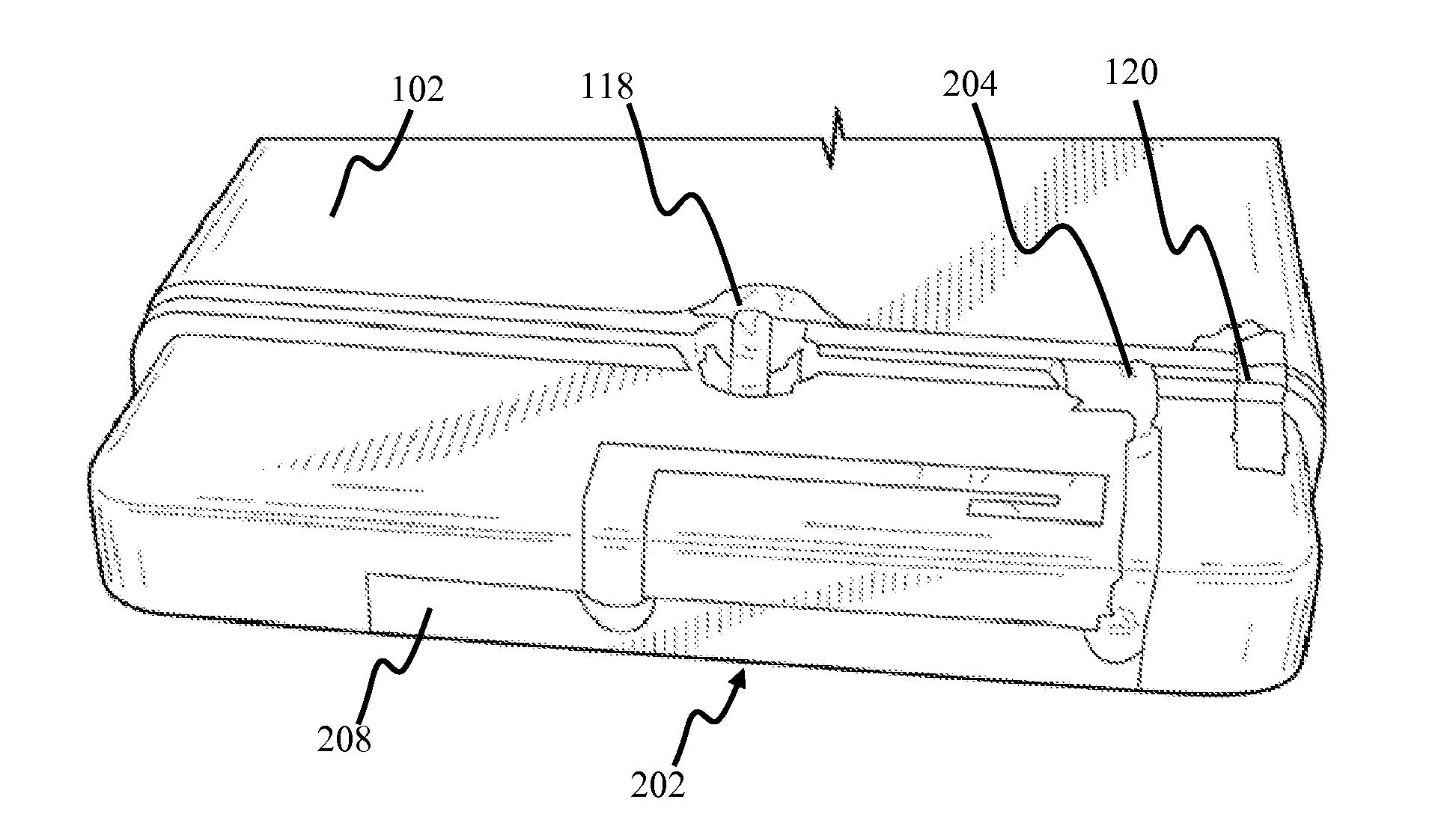
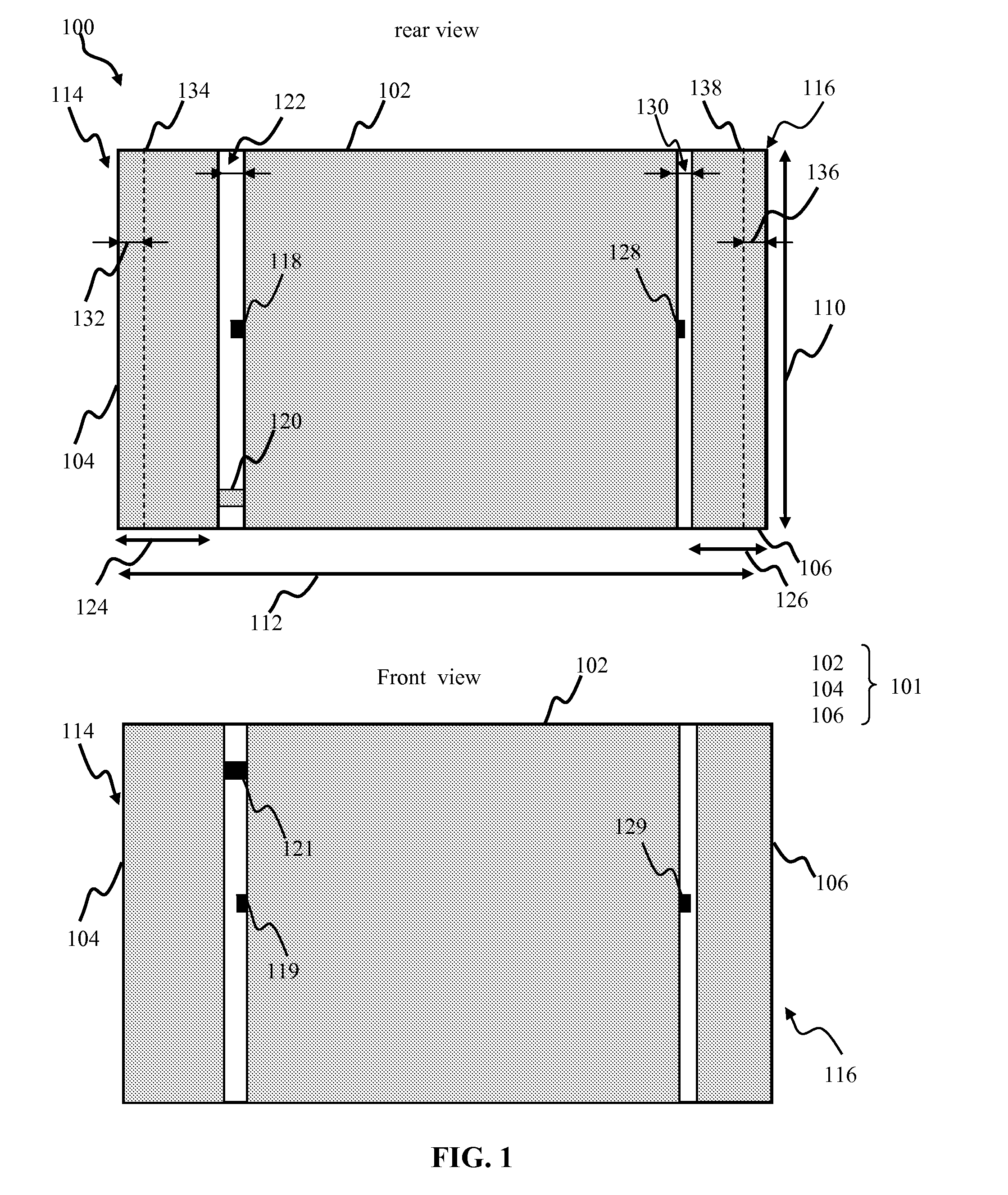
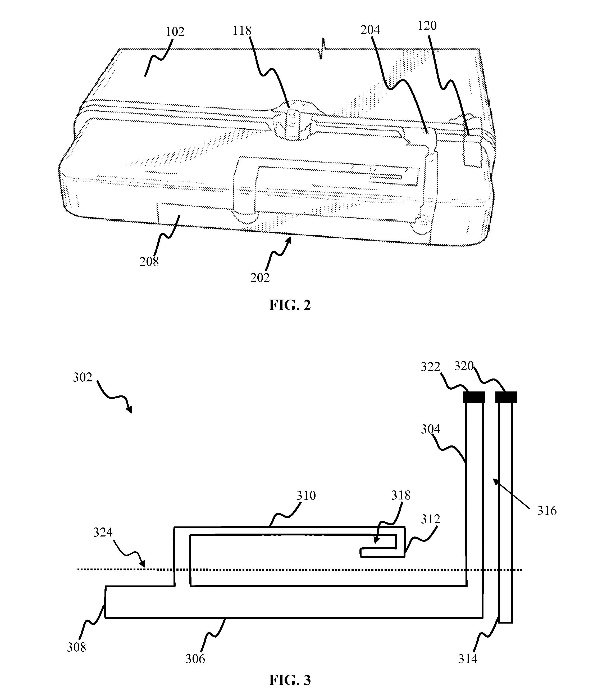
[0038]Reference is now made to the drawings wherein like numerals refer to like parts throughout.

[0039]As used herein, the terms “antenna,”“antenna system,”“antenna assembly”, and “multi-band antenna” refer without limitation to any apparatus or system that incorporates a single element, multiple elements, or one or more arrays of elements that receive / transmit and / or propagate one or more frequency bands of electromagnetic radiation. The radiation may be of numerous types, e.g., microwave, millimeter wave, radio frequency, digital modulated, analog, analog / digital encoded, digitally encoded millimeter wave energy, or the like.

[0040]As used herein, the terms “board” and “substrate” refer generally and without limitation to any substantially planar or curved surface or component upon which other components can be disposed. For example, a substrate may comprise a single or multi-layered printed circuit board (e.g., FR4), a semi-conductive die or wafer, or even a surface of a housing o...


PUM


Abstract

A multiband internal antenna apparatus and methods of tuning and utilizing the same. In one embodiment, the antenna configuration is used within a handheld mobile device (e.g., cellular telephone or smartphone). The device enclosure is fabricated from a conductive material and has two parts: the main portion, housing the device electronics and ground plane, and the antenna cap, which substantially envelops a directly fed radiator structure of the antenna. Electromagnetic coupling of the cap portion to the device feed effects formation of a parasitic antenna radiator in a lower frequency band. The cap portion is separated from the main portion by a narrow gap, extending along circumference of the device, and is grounded at a location selected to cause desired resonance and to widen antenna bandwidth. In one implementation, a second parasitic radiator is disposed proximate the directly feed radiator to further expand antenna frequency bands of operation.

Description

COPYRIGHT[0001]A portion of the disclosure of this patent document contains material that is subject to copyright protection. The copyright owner has no objection to the facsimile reproduction by anyone of the patent document or the patent disclosure, as it appears in the Patent and Trademark Office patent files or records, but otherwise reserves all copyright rights whatsoever.FIELD OF THE INVENTION[0002]The present invention relates generally to antenna apparatus for use in electronic devices such as wireless or portable radio devices, and more particularly in one exemplary aspect to an internal multiband antenna for use with conductive enclosures, and methods of tuning and utilizing the same.DESCRIPTION OF RELATED TECHNOLOGY[0003]Internal antennas are an element found in most modern radio devices, such as mobile computers, mobile phones, Blackberry® devices, smartphones, personal digital assistants (PDAs), or other personal communication devices (PCDs). Typically, these antennas ...

Claims


Application Information

Patent Timeline
Patent Type & Authority Applications(United States)
IPC IPC(8): H01Q1/24H01Q5/10H01Q5/371H01Q5/378
CPCH01Q1/243H01Q9/0421H01Q5/378H01Q5/371H01Q9/045
Inventor ISOHATALA, ANNE
Owner PULSE FINLAND
Why Eureka
Try Eureka