
Emergency core cooling system (ECCS) for nuclear reactor employing closed heat transfer pathways

a cooling system and nuclear reactor technology, applied in the fields of nuclear reactor arts, nuclear power generation arts, nuclear safety arts, etc., can solve the problems of piping presenting a potential safety hazard, primary leakage, pressure vessel depressurizing and possibly leaking primary coolan

Inactive Publication Date: 2013-06-20
BWXT NUCLEAR ENERGY
View PDF6 Cites 20 Cited by
  • Summary
  • Abstract
  • Description
  • Claims
  • Application Information

AI Technical Summary

Benefits of technology

The patent describes a nuclear reactor system that includes a pressure vessel and a nuclear reactor core. A containment structure holds the nuclear reactor. A condenser is located outside of the containment structure and includes a plurality of heat pipes that are embedded in the containment structure. The heat pipes have first ends inside the containment structure and second ends outside of the containment structure, which are connected to an ultimate heat sink pool. The technical effect of this system is that it allows for improved heat transfer within the containment structure, reducing the likelihood of fouling and ensuring efficient performance of the nuclear reactor.

Problems solved by technology

In a LOCA, a rupture in the pressure vessel or in connecting piping (e.g., pipes conducting primary coolant to / from an external turbine or steam generator) may cause the pressure vessel to depressurize and possibly leak primary coolant.
This piping presents a potential safety hazard since a break in the pipe may result in a primary leak from containment.
In a LOCA this can result in venting of radioactive primary coolant steam into the outside atmosphere.

Method used


Image

  • Emergency core cooling system (ECCS) for nuclear reactor employing closed heat transfer pathways
  • Emergency core cooling system (ECCS) for nuclear reactor employing closed heat transfer pathways
  • Emergency core cooling system (ECCS) for nuclear reactor employing closed heat transfer pathways

Examples


Embodiment Construction

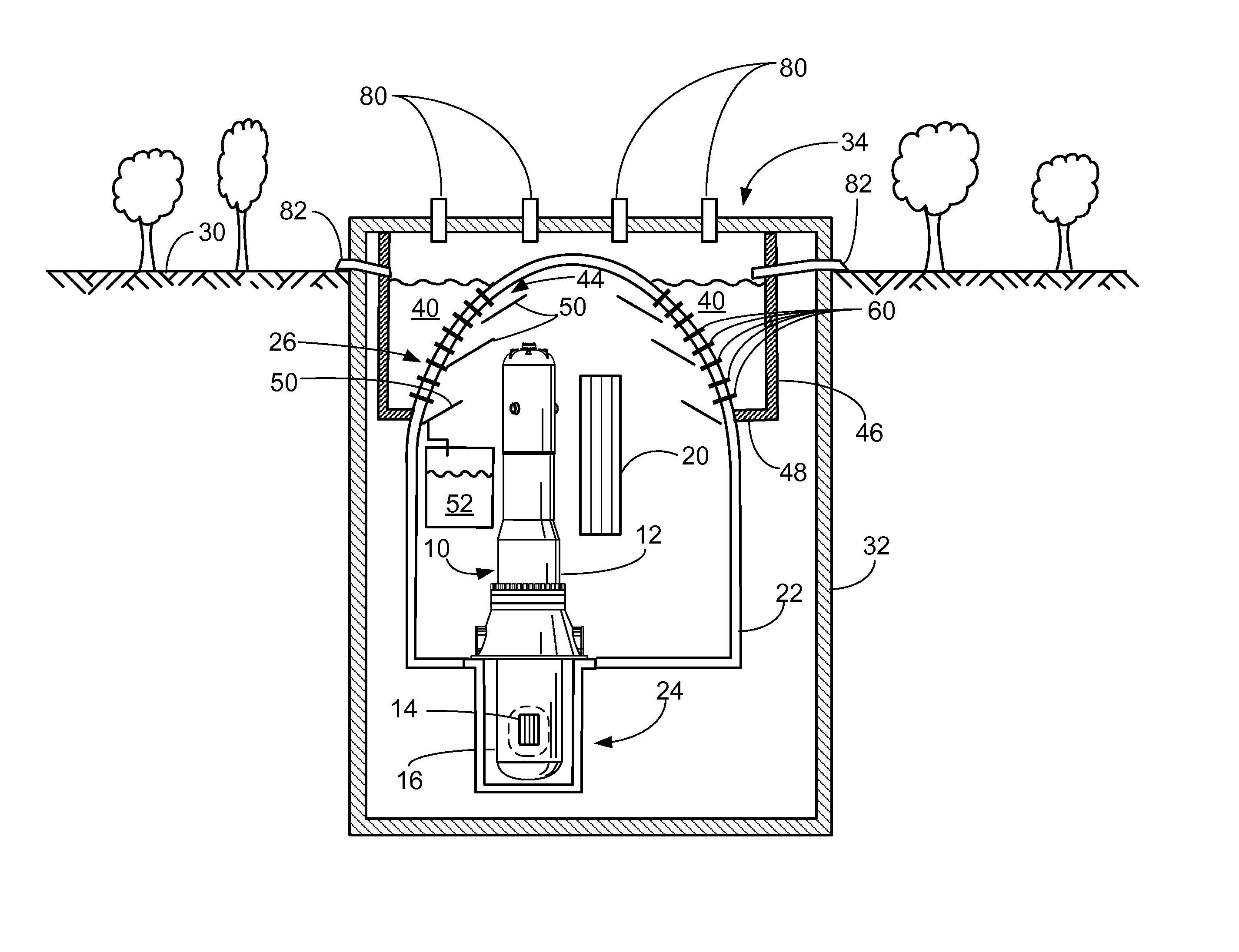
[0015]With reference to FIG. 1, an illustrative nuclear reactor of the pressurized water reactor (PWR) type 10 includes a pressure vessel 12, which in the illustrative embodiment is a cylindrical vertically mounted vessel. (Note that the term “cylindrical” as used herein does not require a mathematically precise cylinder, but rather allows for deviations such as changes in diameter along the length of the cylinder axis, inclusion of vessel penetrations or other localized features, or so forth). A nuclear reactor core 14 is disposed in a lower portion of the pressure vessel 12. (Note that in diagrammatic FIG. 1 the reactor core 14 is revealed by a cutaway 16 in the pressure vessel 12). The reactor core 14 includes a mass of fissile material, such as a material containing uranium oxide (UO2) that is enriched in the fissile 235U isotope, in a suitable matrix material. In a typical configuration, the fissile material is arranged as “fuel rods” arranged in a core basket. The pressure ves...


PUM


Abstract

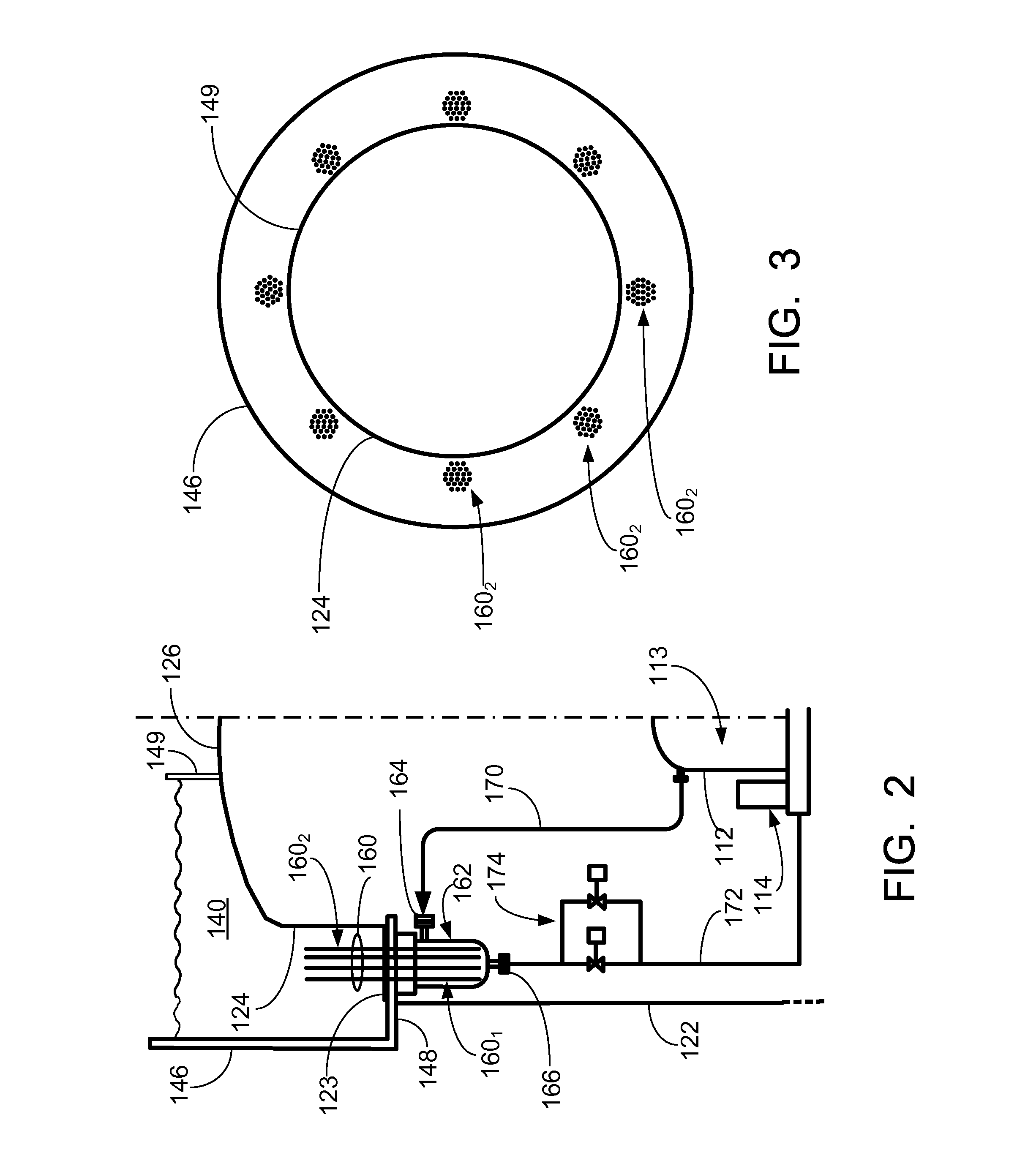
A containment structure contains an interior volume, and a nuclear reactor is disposed in the interior volume. An ultimate heat sink pool is disposed outside of the containment structure. A condenser includes a plurality of closed-path heat pipes or closed-path thermosiphons having first ends and opposite second ends. The closed-path heat pipes or closed-path thermosiphons are embedded in the containment structure with the first ends protruding into the interior volume and the second ends protruding outside of the containment structure.

Description

BACKGROUND[0001]The following relates to the nuclear reactor arts, nuclear power generation arts, nuclear safety arts, and related arts.[0002]Nuclear reactor safety centers upon maintaining the radioactive core in an immersed condition with adequate heat removal. During normal operation, the reactor core is disposed in a sealed reactor pressure vessel that is filled (or mostly filled) with primary coolant (e.g., light water, in the case of a light water reactor). Heat removal is provided by circulation of the primary coolant through a “heat sink”. In the case of a nuclear power plant, the “heat sink” usually takes the form of a steam generator or turbine. In a conventional boiling water reactor (BWR) the primary coolant is converted to steam inside the pressure vessel and piped out to directly drive a turbine where the act of performing useful work on the turbine cools the steam. In a conventional pressurized water reactor (PWR) primary coolant in a subcooled liquid phase is piped i...

Claims


Application Information

Patent Timeline
Patent Type & Authority Applications(United States)
IPC IPC(8): G21C9/00F28D15/04
CPCG21C15/18G21C13/02Y02E30/40G21D3/04G21D1/00G21C15/257G21C15/26Y02E30/00Y02E30/30
Inventor BINGHAM, BILLY E.
Owner BWXT NUCLEAR ENERGY
Learn More