Optical fiber transmission switching device and control method thereof

Inactive Publication Date: 2013-06-20
OPTOMEDIA TECH
View PDF2 Cites 12 Cited by
  • Summary
  • Abstract
  • Description
  • Claims
  • Application Information

AI Technical Summary

Benefits of technology

[0030]Under the condition to be compatible to the currently existing connectors, the optical fiber transmission switching device of the present invention provides an additional transceiver as a redundant data transmission channel. The size of the transceiver is reduced and the number of the sockets

Problems solved by technology

However, this automatic switching device can not monitor the status of the redundant optical channel, such that automatic switching device can not determine whether the redundant optical channel functions normally.
If the redundant optical channel also fails, not only data transmissi

Method used


Image

  • Optical fiber transmission switching device and control method thereof
  • Optical fiber transmission switching device and control method thereof
  • Optical fiber transmission switching device and control method thereof

Examples


Embodiment Construction

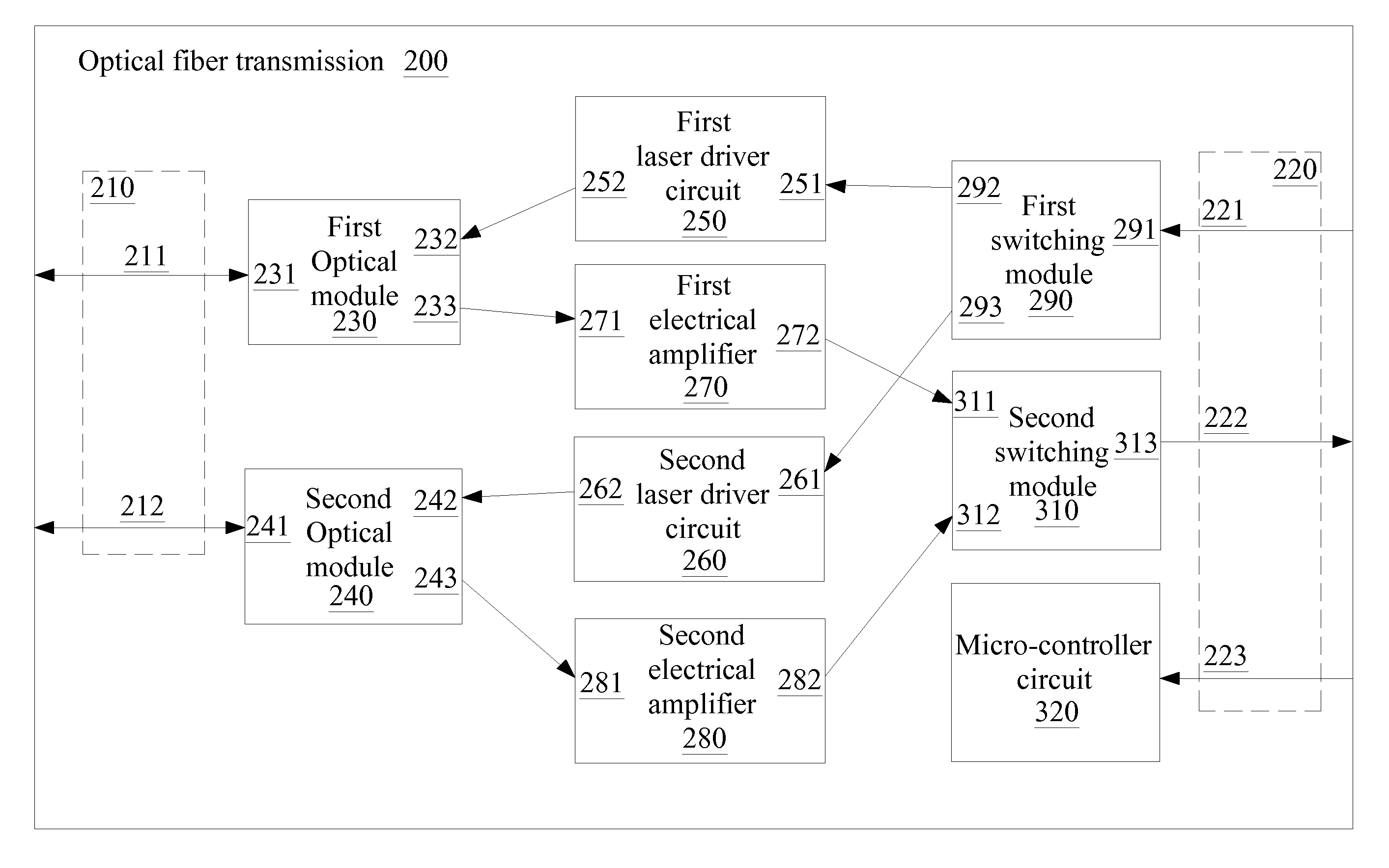
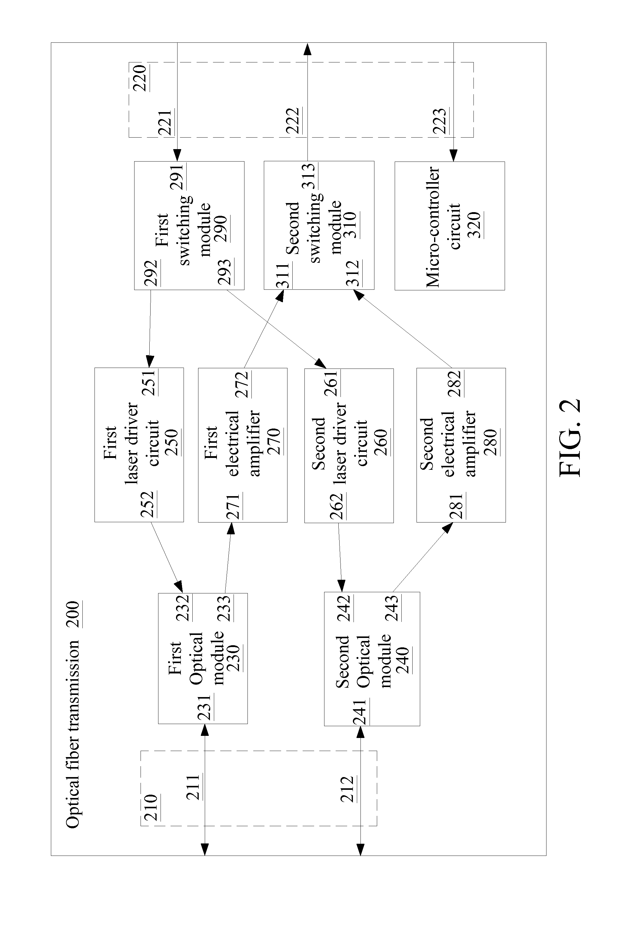
[0041]Refer to FIG. 2, a schematic diagram of the optical fiber transmission switching device 200 in the present invention. The optical fiber transmission switching device 200 is applicable to an optical network, for example a passive optical network (PON).

[0042]The channel-end interface 210 includes a first transmission port 211 and a second transmission port 212 coupling to the optical channels of the optical network to transmitting optical signals.

[0043]The terminal-end interface 220 includes a terminal-end input port 221 and a terminal-end output port 222, for transmitting electrical signals between the optical line terminal (OLT) and the optical network unit (ONU), so as to perform data transmission and system control. In one example, the terminal-end interface 220 includes twenty pins interface applicable to small form-factor pluggable (SFP) transceiver multi-source agreement (MSA).

[0044]The first optical module 230 and the second optical module 240 respectively include a bi-d...


PUM


Abstract

An optical fiber transmission switching device includes a first transmission port; a second transmission port; a terminal-end input port; a terminal-end output port; a first and a second optical module respectively including an electrical input port, an electrical output port, and a bi-directional optical port, wherein the two bi-directional optical ports are coupled to the first and the second transmission port respectively; a first and a second laser driver circuit respectively coupled to the first and the second optical module; a first and a second electrical amplifier respectively coupled to the first and the second optical module; a first switching module coupled to the terminal-end input port and the first and the second laser driver circuit; a second switching module coupled to the first and the second electrical amplifier and the terminal-end output port.

Description

CROSS-REFERENCE TO RELATED APPLICATIONS[0001]This application claims the benefit of the filing date priority of a co-pending U.S. Provisional Application No. 61 / 565,493 filed on Nov. 30, 2011, the disclosure of which is incorporated herein by reference in its entirety.BACKGROUND OF THE INVENTION[0002]1. Field of the Invention[0003]The present invention relates to optical communications, and more particularly, to an optical fiber transmission switching device.[0004]2. Related Art[0005]Among the recent optical communication products, the small form factor (SFF) optical transceiver module is further evolved to the small form factor pluggable (SFP) optical transceiver module. The product manufactured according to SFP standard has a more compact volume with the hot-pluggable function. Therefore, through the utilization of SFP transceiver, more transceiver modules can be installed in the same space. Without turning OFF the facility, the modules can be removed and replaced, such that it is...

Claims


Application Information

Patent Timeline
IPC IPC(8): G02B6/35H04B10/03
CPCG02B6/35H04B10/40H04B10/032H04B10/03
Inventor CHOU, HUI TSUOLYNN, JOHN
Owner OPTOMEDIA TECH
Why Eureka
Try Eureka