System and apparatus for cell treatment

Active Publication Date: 2013-06-20
THE GENERAL HOSPITAL CORP
View PDF8 Cites 44 Cited by
  • Summary
  • Abstract
  • Description
  • Claims
  • Application Information

AI Technical Summary

Benefits of technology

[0008]Embodiments of the present invention provide methods, systems, and apparatuses for processing biological cells or tissues that have been removed from a subject, and which may optionally be transplanted into the same or a different subject. Such processing can include removal of impurities, e.g., excess liquids, free lipi

Problems solved by technology

Decreased viability may result from tissue or cell damage caused by relatively high flow rates, pressures, injection ve

Method used


Image

  • System and apparatus for cell treatment
  • System and apparatus for cell treatment
  • System and apparatus for cell treatment

Examples


example 1

An Apparatus for Collecting a Biological Sample, e.g., Adipose Tissue, for Subsequent Re-Use

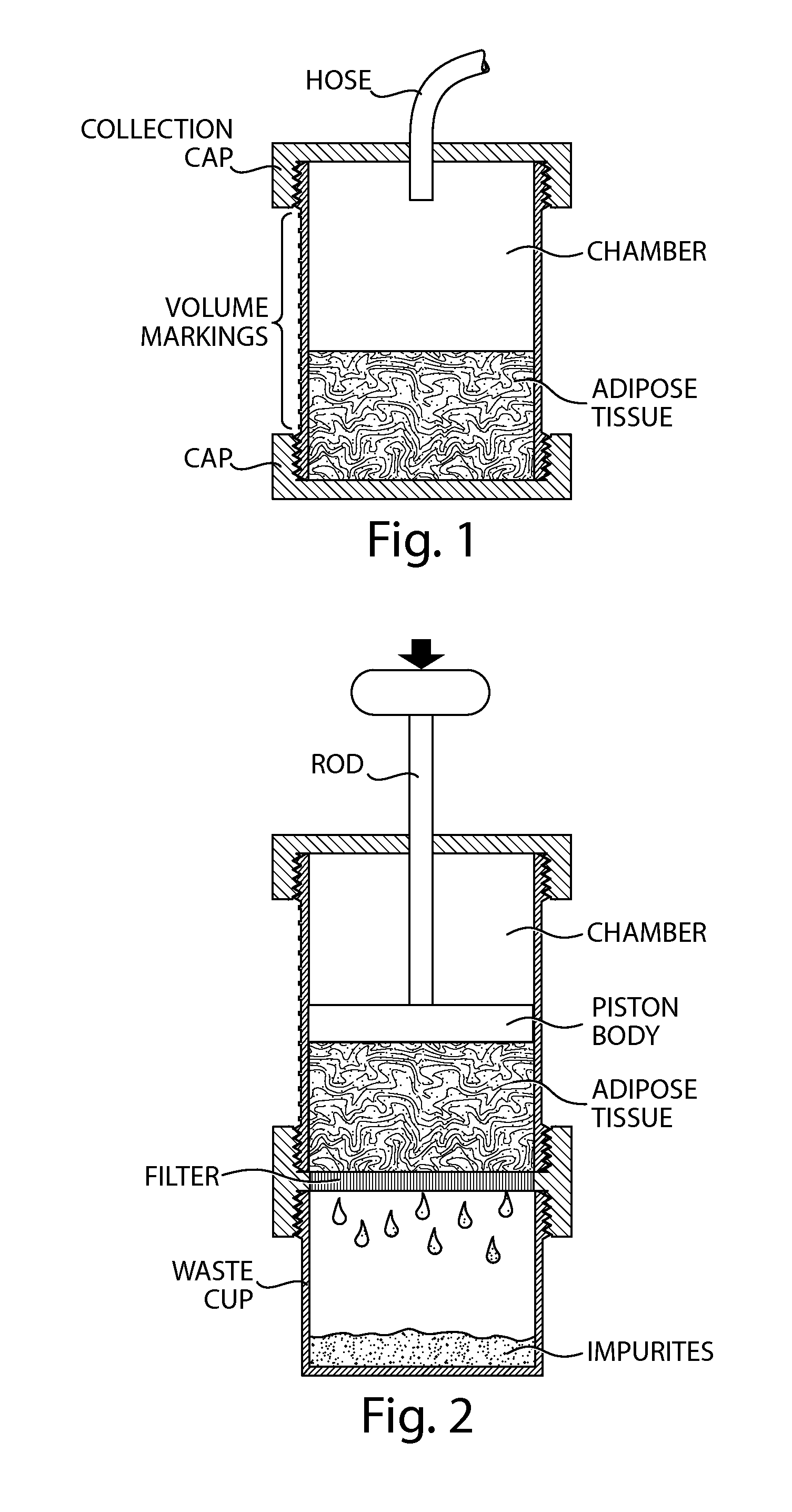
[0111]FIG. 1 depicts an apparatus for collecting a biological sample, e.g., adipose tissue, for subsequent re-use. The apparatus includes a chamber that is cylindrical in shape. The chamber is provided with a threaded section. However, other coupling arrangements may be used at either or both ends. Other coupling arrangements that may be used include, e.g., pressure-fit connectors, clamps, or the like. O-rings or other sealing arrangements can also be provided to form a leakproof and / or pressure-resistant seal between each chamber end and an end-piece that is configured to be removably attached thereto. Optionally, such end-pieces may be permanently affixed to an end of the chamber and / or configured to be affixed to other end-pieces. The chamber may optionally include volumetric markings to indicate the amount of material contained therein, as shown in FIG. 1. In this example, adipose cells (...

example 2

A Filter Apparatus with a Hand-Operated Plunger Arrangement

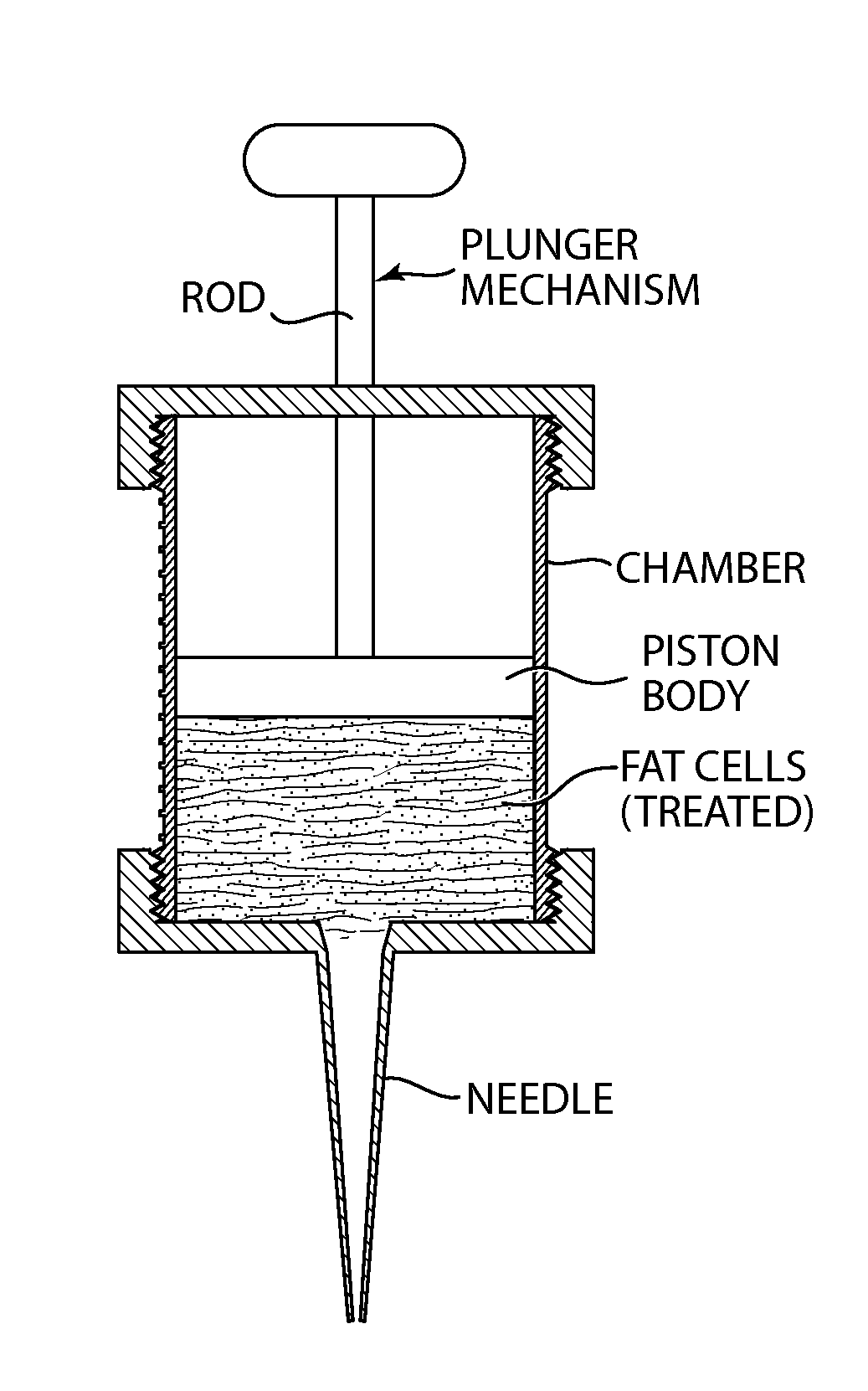
[0112]In another example, a filter, as shown in FIG. 2, can be affixed to the distal end of the chamber depicted in FIG. 1. For example, the collection cap as shown in FIG. 1, if used, is removed, and a plunger mechanism is affixed to the proximal end of the chamber. The chamber is then inverted, such that the distal end of the chamber is on top, and the filter arrangement is affixed to the distal end of the chamber. In certain embodiments, a waste cup is affixed to the chamber, as shown in FIG. 2, or the filter arrangement and waste cup are provided as a single component. An end-piece that includes a hand-operated plunger mechanism is affixed to the proximal end of the chamber.

example 3

A Plunger Arrangement with a Frictional Interface

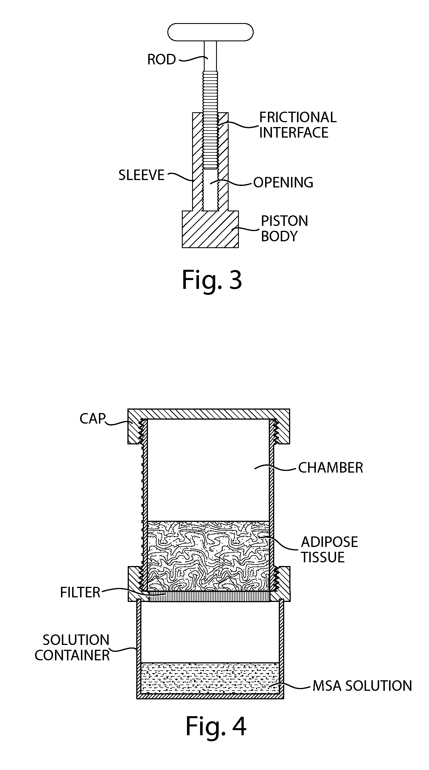
[0113]An exemplary force-limiting plunger arrangement that may be used with certain embodiments of the present invention is shown in FIG. 3. This plunger arrangement includes a rod configured to fit into an opening that extends at least partially along a longitudinal axis of a sleeve. A piston body is affixed to a distal end of the sleeve, or it may be formed as an integral part of the sleeve. The rod and sleeve may have circular cross-section shapes, or other cross-sectional shapes may be used (e.g., hexagonal, octagonal, square, or triangular shapes).

[0114]A clutch arrangement, e.g., a frictional interface or the like, can be provided between the outer surface of the rod and the inner surface in the sleeve when the rod is inserted partially into the sleeve, as shown in FIG. 3. In operation, pushing down on the rod with a relatively small force will allow the rod to frictionally grip the surrounding portion of the sleeve and transmit...


PUM


Abstract

The present invention relates to systems and apparatuses for improving quality and viability of biological material, such as harvested adipose cells, stem cells, or other cells or biological components, by treatment of the biological material with membrane-repairing/stabilizing agents or the like and/or mechanical removal of components, such as impurities and/or excess treatment agents. The present invention further relates to systems and apparatuses for transplanting tissue, such as adipose tissue.

Description

RELATED APPLICATIONS[0001]This application claims the benefit under 35 U.S.C. §119(e) of U.S. provisional application, U.S. Ser. No. 61 / 371,400, filed Aug. 6, 2010, and entitled “SYSTEM AND APPARATUS FOR CELL TREATMENT,” the entire contents of which are incorporated herein by reference.FIELD OF THE INVENTION[0002]The present invention relates to methods, systems and apparatuses for processing biological material, such as harvested adipose tissue, adipose cells (adipocytes), stem cells, or other cells or tissues.BACKGROUND INFORMATION[0003]Adipose tissue that is harvested from the body can be re-introduced or autologously transplanted, e.g., as a filler material for cosmetic purposes such as augmentation of certain body features. Adipose tissue may also be used for certain reconstructive and / or functional procedures such as facial reconstruction, breast reconstruction or augmentation, and vocal cord injection to improve voice function. The adipose tissue can be harvested using conven...

Claims


Application Information

Patent Timeline
IPC IPC(8): C12N5/071A61M5/172A61M5/145
CPCA61M5/14526C12M47/04C12N5/0653A61M5/1723C12M45/02
Inventor AUSTEN, JR., WILLIAM G.
Owner THE GENERAL HOSPITAL CORP
Why Eureka
Try Eureka