Internal combustion engine diagnostic device and internal combustion engine diagnostic method

a technology for internal combustion engines and diagnostic devices, which is applied in the direction of electrical control, process and machine control, instruments, etc., can solve the problems of not being able to judge whether the air-fuel ratio in the respective cylinder is favorable or not, and it is not possible to identify which cylinders are suffering a malfunction, so as to prevent the effect of being adversely affected, adversely affecting the durability of the ignition plug, and adversely affecting the durability of the catalys

Active Publication Date: 2013-06-20
HONDA MOTOR CO LTD
View PDF16 Cites 16 Cited by
  • Summary
  • Abstract
  • Description
  • Claims
  • Application Information

AI Technical Summary

Benefits of technology

[0020]According to the present invention, if the number of misfires of either one of the cylinders or the total of the numbers of misfires of the cylinders exceeds a predetermined value while the air-fuel ratios which are being changed stepwise, the protector stops changing the air-fuel ratios stepwise to protect an ignition plug or an exhaust gas purification filter. Consequently, the ignition plug or the exhaust gas purification filter is prevented from being adversely affected depending on the predetermined value.
[0021]Specifically, as described above, when misfires occur frequently in a cylinder, the temperature in the combustion chamber of the cylinder drops, tending to smoke the ignition plug, i.e., depositing more soot on the ignition plug. As a result, it is highly likely for the cylinder to cause more misfires due to the deposited soot, and it may not be possible to judge accurately the number of misfires which are caused by a change in the air-fuel ratio. The soot deposited on the ignition plug may possibly adversely affect the durability of the ignition plug. When misfires occur, unburned gases which have not been combusted in the combustion chamber are discharged from the internal combustion engine, and then may be ignited in the catalyst by the heat of the exhaust gas purification filter (catalyst). If this phenomenon happens frequently, the catalyst may possibly be heated to an excessively high temperatu...

Problems solved by technology

However, it is not possible to identify which cylinder is suffering a malfunction.
According to JP03-189371A, though a malfunctioning cylind...

Method used


Image

  • Internal combustion engine diagnostic device and internal combustion engine diagnostic method
  • Internal combustion engine diagnostic device and internal combustion engine diagnostic method
  • Internal combustion engine diagnostic device and internal combustion engine diagnostic method

Examples


embodiment

A. Embodiment

1. Configuration

(1) Overall Configuration:

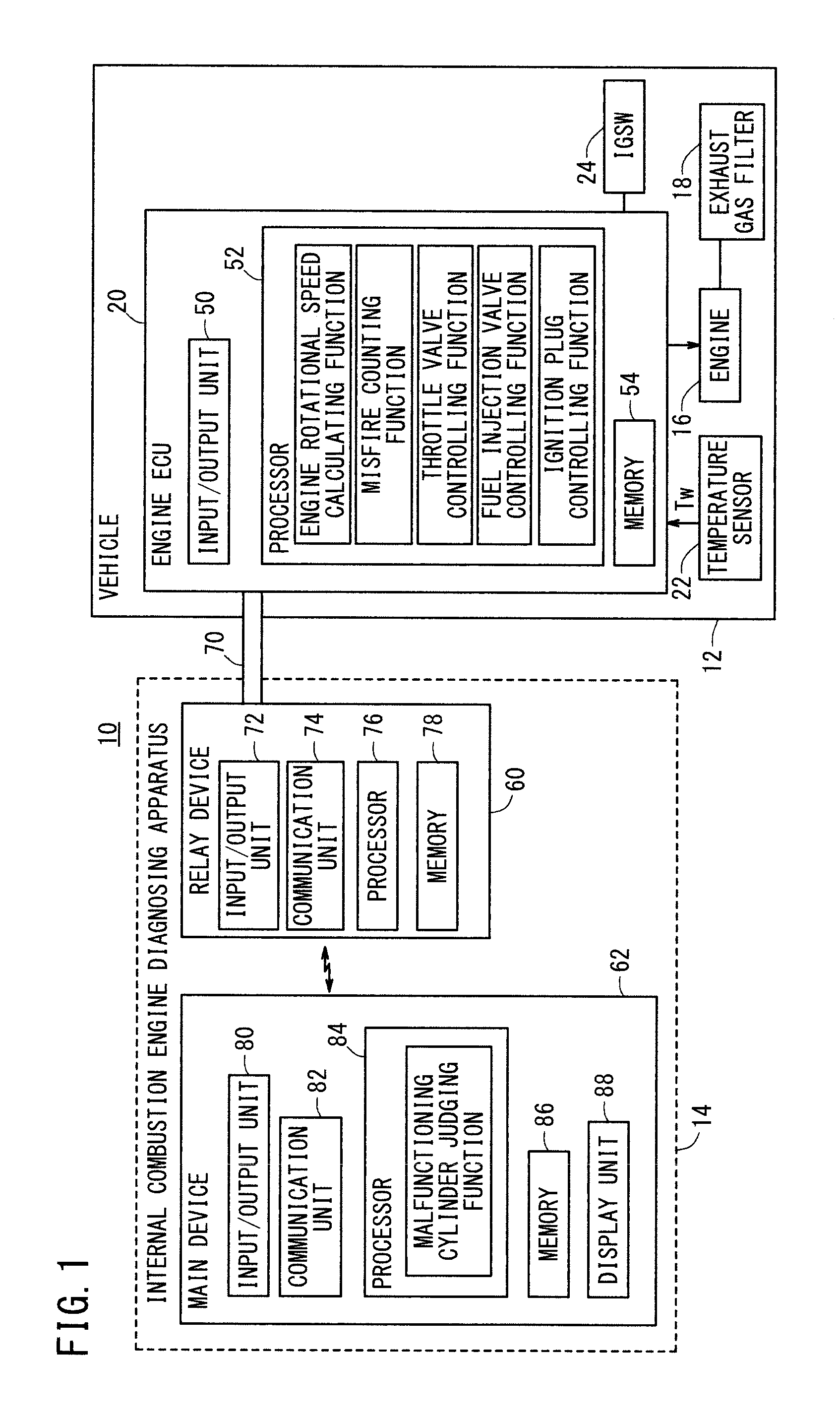
[0058]FIG. 1 is a block diagram showing the general configuration of an internal combustion engine diagnosing system 10 (hereinafter referred to as “system 10”) having an internal combustion engine diagnosing apparatus 14 (hereinafter referred to as “diagnosing apparatus 14”) according to an embodiment of the present invention. The system 10 has a vehicle 12 including an engine 16 to be diagnosed and the diagnosing apparatus 14 which diagnoses the engine 16.

(2) Vehicle 12:

(a) Overall Configuration:

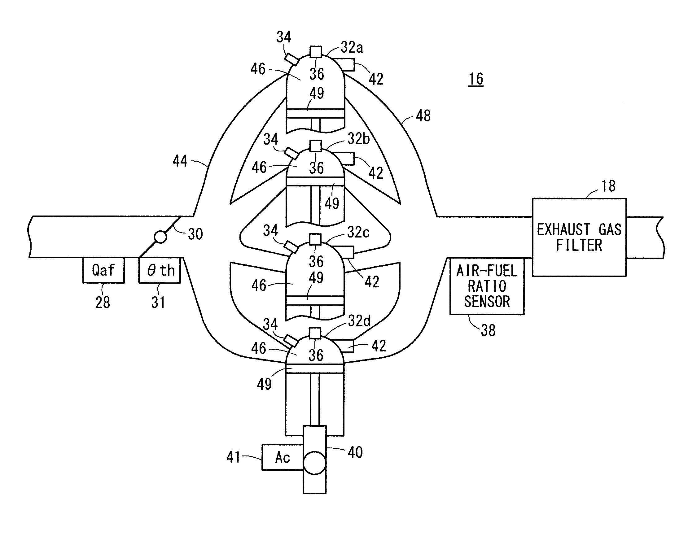
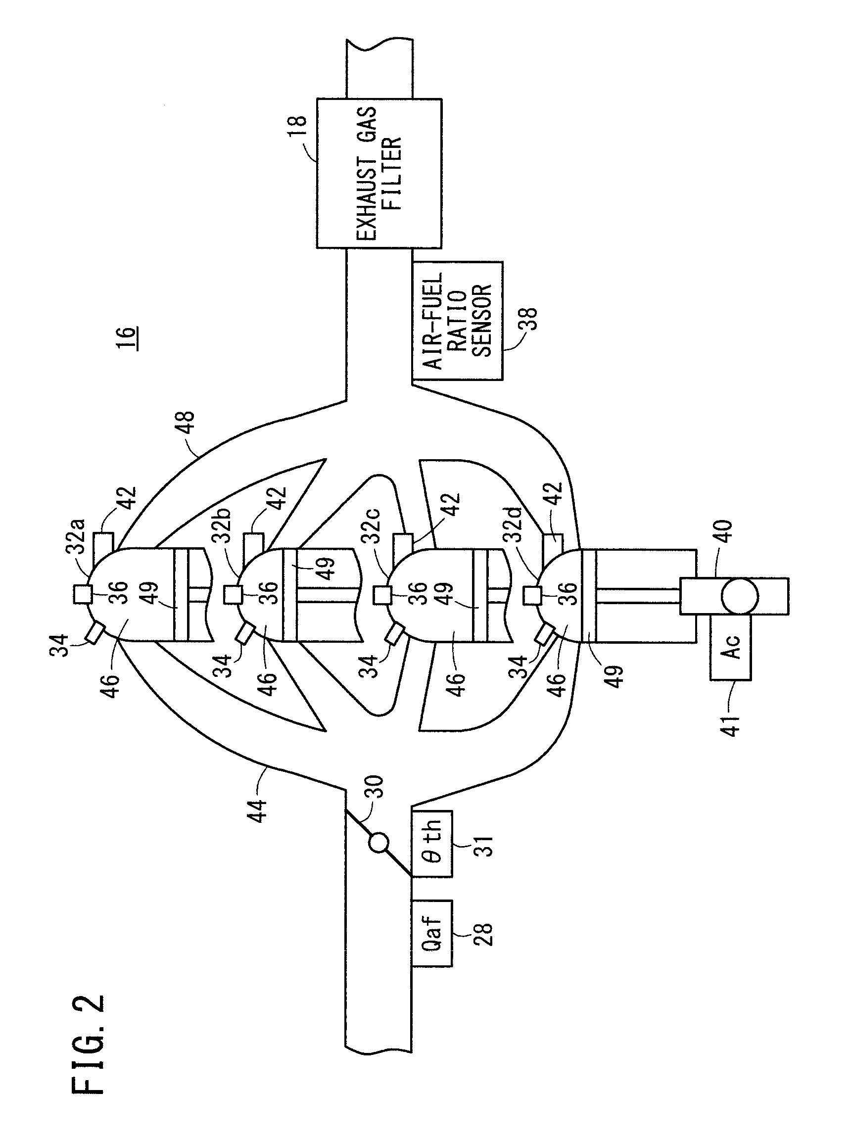
[0059]The vehicle 12 includes, in addition to the engine 16, an exhaust gas filter 18 (hereinafter referred to as “filter 18”) for purifying exhaust gases from the engine 16, an engine electronic control unit 20 (hereinafter referred to as “engine ECU 20”) for controlling the output power of the engine 16, a temperature sensor 22 for detecting the temperature Tw [° C.] of the coolant of the engine 16, and an ignition switch 24 (hereina...


PUM


Abstract

An internal combustion engine diagnostic device and an internal combustion engine diagnostic method identify an abnormal cylinder having an abnormal air-fuel ratio among a plurality of cylinders during the operation of an internal combustion engine. The internal combustion engine diagnostic device comprises: an air-fuel ratio control unit for changing the air-fuel ratio in a stepwise manner by controlling a fuel injection amount adjusting means that adjusts the fuel injection amount of each of the plurality of cylinders; and an abnormal cylinder identification unit for identifying an abnormal cylinder on the basis of the relationship between each air-fuel ratio changed in a stepwise manner and the number of misfires occurring in the plurality of cylinders, the number being counted by a misfire counter for each air-fuel ratio changed in a stepwise manner.

Description

TECHNICAL FIELD[0001]The present invention relates to an internal combustion engine diagnosing apparatus (device) and an internal combustion engine diagnosing method for identifying a malfunctioning cylinder having an abnormal air-fuel ratio among a plurality of cylinders of an internal combustion engine while the internal combustion engine is in operation.BACKGROUND ART[0002]While internal combustion engines on automobiles or the like are in operation, it has been customary from the standpoint of exhaust gas purification to add an air-fuel ratio sensor and control the amount of a supplied fuel for maintaining a good air-fuel ratio according to an air-fuel ratio feedback control process.[0003]Even if an exhaust gas itself is kept in a favorable condition, however, variation in the air-fuel ratios in different cylinders tend to lower the purification ratio of a catalyst which purifies the exhaust gas. Accordingly, efforts have been made to monitor variation in the air-fuel ratios in ...

Claims


Application Information

Patent Timeline
IPC IPC(8): F02D41/22
CPCF02D41/0085F02D41/1456Y02T10/40F02D2200/1015F02D41/22
Inventor ITO, HIROSHIABE, TAKAYUKIKATO, MASAHIROOHNO, TETSUYA
Owner HONDA MOTOR CO LTD
Why Eureka
Try Eureka