Ceramic heater and manufacturing method therefor, and heating apparatus

Inactive Publication Date: 2013-06-27
NGK SPARK PLUG CO LTD
View PDF23 Cites 8 Cited by
  • Summary
  • Abstract
  • Description
  • Claims
  • Application Information

AI Technical Summary

Benefits of technology

[0028]As in the case of the above configuration 6, in the case where power is supplied to the heat-generating element in such a manner as to raise the surface temperature of a heating portion of the substrate corresponding to the heat-generating portion from room temperature to 1,000° C. within one second; i.e., in the case where the heat-generating element executes ultrahigh-speed temperature raising, an electrical disconnection is more likely to occur in the heat-generating element (heat-generating portion). However, even in such a case, by use of the ceramic heater manufactured b

Problems solved by technology

When the conventional ceramic heater is energized for heating under the condition of ultrahigh-speed temperature raising, even though the he

Method used


Image

  • Ceramic heater and manufacturing method therefor, and heating apparatus
  • Ceramic heater and manufacturing method therefor, and heating apparatus
  • Ceramic heater and manufacturing method therefor, and heating apparatus

Examples


Embodiment Construction

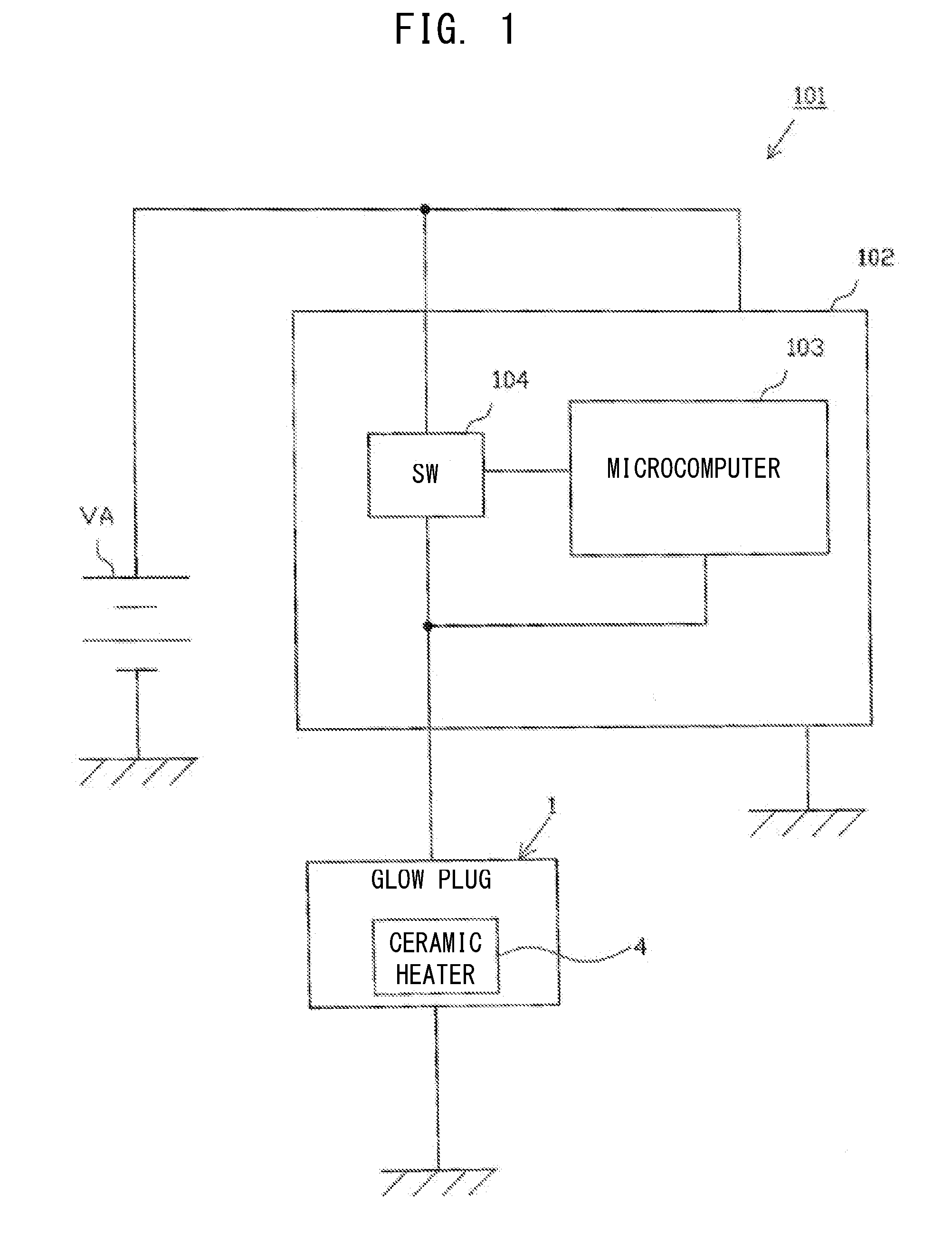
[0048]An embodiment of the present invention will next be described with reference to the drawings. FIG. 1 is a block diagram showing the schematic configuration of a heating apparatus 101.

[0049]The heating apparatus 101 includes a ceramic glow plug 1 (hereinafter, referred to as the “glow plug 1”) having a ceramic heater 4, and a glow control unit (GCU) 102 (an energization control unit) to control energization of the glow plug 1. FIG. 1 shows only a single glow plug 1. However, an actual engine has a plurality of cylinders, and the glow plug 1 and a switch 104, which will be described later, are provided for each of the cylinders.

[0050]The GCU 102 operates by power supplied from a battery VA and includes a microcomputer 103 having a CPU, a ROM, a RAM, etc., and the switch 104 adapted to turn ON / OFF the supply of power to the glow plug 1 from the battery VA.

[0051]The GCU 102 controls energization of the glow plug 1 under PWM control such that the switch 104 turns ON / OFF the supply ...


PUM

PropertyMeasurementUnit
Temperatureaaaaaaaaaa
Timeaaaaaaaaaa
Fracture toughnessaaaaaaaaaa

Abstract

A ceramic heater having a substrate and a heat-generating element. The substrate is formed from an electrically insulating ceramic and extends rearward from the forward end of the ceramic heater in the direction of the axis. The heat-generating element has a heat-generating portion formed from an electrically conductive ceramic which contains silicon nitride and an electrically conductive material, disposed in a forward end portion of the substrate, and having a shape resembling the letter U as viewed along the direction of the axis. The heat-generating portion has a fracture toughness of 4.3 MPa·m0.5 or more.

Description

FIELD OF THE INVENTION[0001]The present invention relates to a ceramic heater in which a heat-generating element is held in a substrate, to a method of manufacturing the ceramic heater, and to a heating apparatus having the ceramic heater.BACKGROUND OF THE INVENTION[0002]Conventionally, a glow plug used, for example, to help startup of a diesel engine includes a tubular metallic shell and a heater having an incorporated heat-generating element which generates heat through energization. The heater may be a ceramic heater. The ceramic heater is configured such that a heat-generating element made of electrically conductive ceramic is held in a substrate made of an electrically insulating ceramic (refer to, for example, Japanese Patent Application Laid-Open (kokai) No. 2006-351446).[0003]Meanwhile, in view of a desire to reduce emissions, preferably, the interior of a combustion chamber is quickly raised to a high temperature. Thus, a recently proposed ceramic heater employs a heat-gene...

Claims


Application Information

Patent Timeline
IPC IPC(8): F23Q7/00
CPCF23Q7/001Y10T29/49083H05B2203/027H05B2203/017H05B3/141
Inventor KAN, YOHEI
Owner NGK SPARK PLUG CO LTD
Why Eureka
Try Eureka