High-strength electric resistance welded steel tube and production method therefor
- Summary
- Abstract
- Description
- Claims
- Application Information
AI Technical Summary
Benefits of technology
Problems solved by technology
Method used
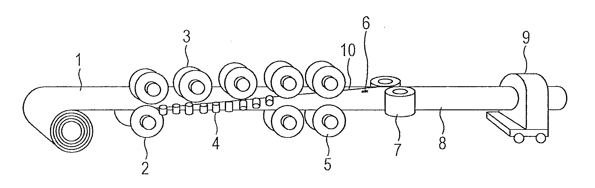
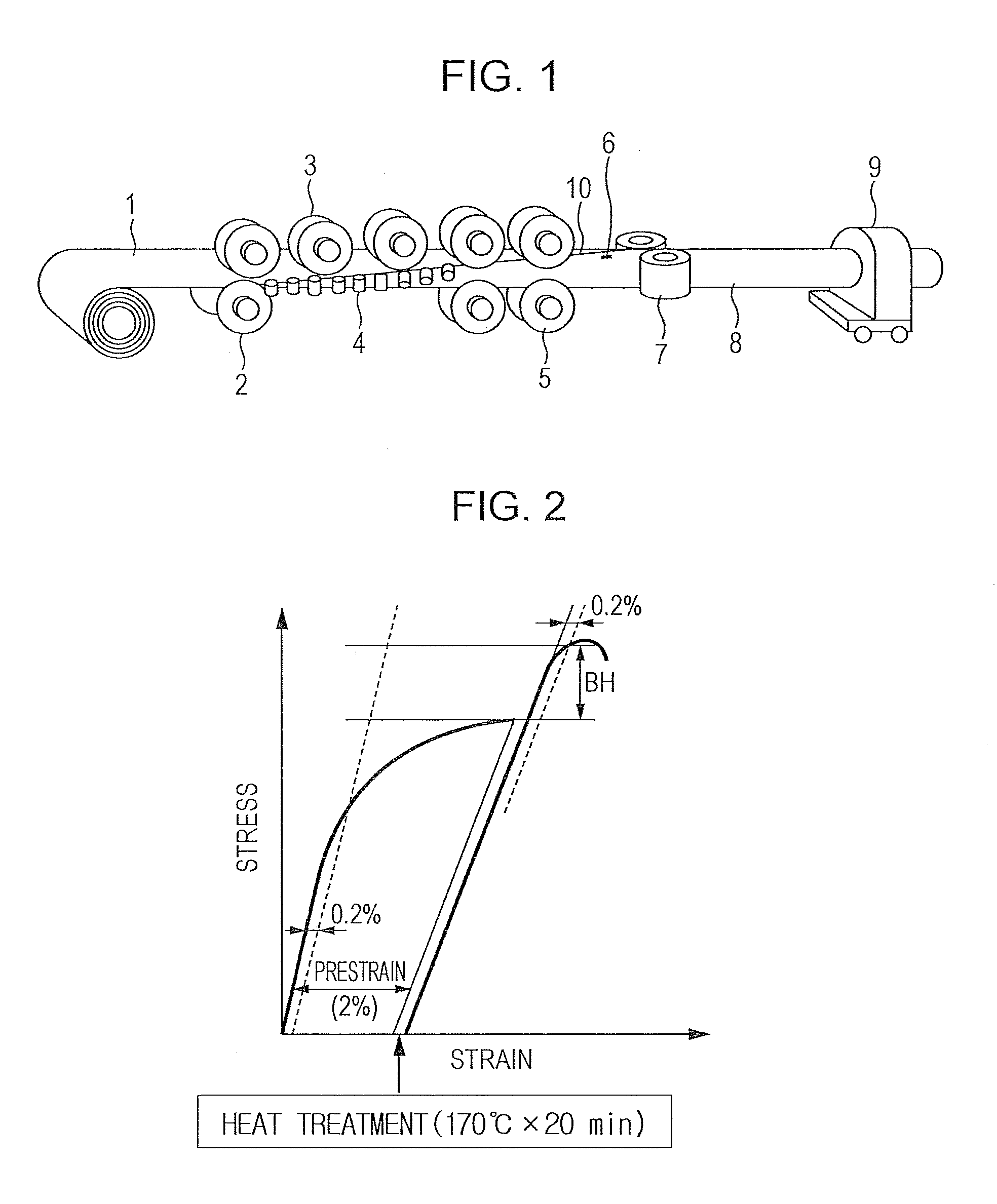
Image

Examples
examples
[0074]Molten steel samples indicated in Table 1 are refined in a converter and continuously casted into slabs (steels). These slabs (steels) are subjected to a hot-rolling process under conditions indicated in Table 2 to form hot-rolled sheets (thickness: 2.4 to 3.0 mm), followed by pickling. The hot-rolled sheets were subjected to a cold-rolling process of cold-rolling the sheets into cold-rolled sheets, and the cold-rolled sheets were subjected to an annealing process under conditions shown in Table 2 to form cold-rolled annealed sheets (thickness: 1.2 to 1.8 mm). As a result, materials for steel tubes were obtained. Test specimens were taken from the obtained materials for steel tubes and structural observation and a tensile test were carried out. The test methods were as follows.
Structural Observation
[0075]Test specimens for structural observation were taken from the materials for steel tubes. Sections of the test specimens taken in the rolling direction were polished, corroded ...
PUM
| Property | Measurement | Unit |
|---|---|---|
| Temperature | aaaaa | aaaaa |
| Temperature | aaaaa | aaaaa |
| Temperature | aaaaa | aaaaa |
Abstract
Description
Claims
Application Information
 - R&D
- Intellectual Property
- Life Sciences
- Materials
- Tech Scout
- Unparalleled Data Quality
- Higher Quality Content
- 60% Fewer Hallucinations
Browse by: Latest US Patents, China's latest patents, Technical Efficacy Thesaurus, Application Domain, Technology Topic, Popular Technical Reports.
© 2025 PatSnap. All rights reserved.Legal|Privacy policy|Modern Slavery Act Transparency Statement|Sitemap|About US| Contact US: help@patsnap.com