Radiographic image detector, radiographic imaging apparatus, radiographic imaging system

a radiographic imaging and detector technology, applied in the field of radiographic imaging detectors, radiographic imaging apparatuses and radiographic imaging systems, can solve problems such as uneven pixel positions and drop in sensitivity

Active Publication Date: 2013-06-27
FUJIFILM CORP
View PDF3 Cites 8 Cited by
  • Summary
  • Abstract
  • Description
  • Claims
  • Application Information

AI Technical Summary

Benefits of technology

[0036]Thus according to the above aspects, the present invention may image radiographic images at a fast rate, and may maintain even resolut

Problems solved by technology

However, simply reducing the pixel size may lead to a drop in sensitivity due to the proportional relationship to surface area in a radiation detection device.
However, in pixel summing of plural hexagonal

Method used


Image

  • Radiographic image detector, radiographic imaging apparatus, radiographic imaging system
  • Radiographic image detector, radiographic imaging apparatus, radiographic imaging system
  • Radiographic image detector, radiographic imaging apparatus, radiographic imaging system

Examples


first exemplary embodiment

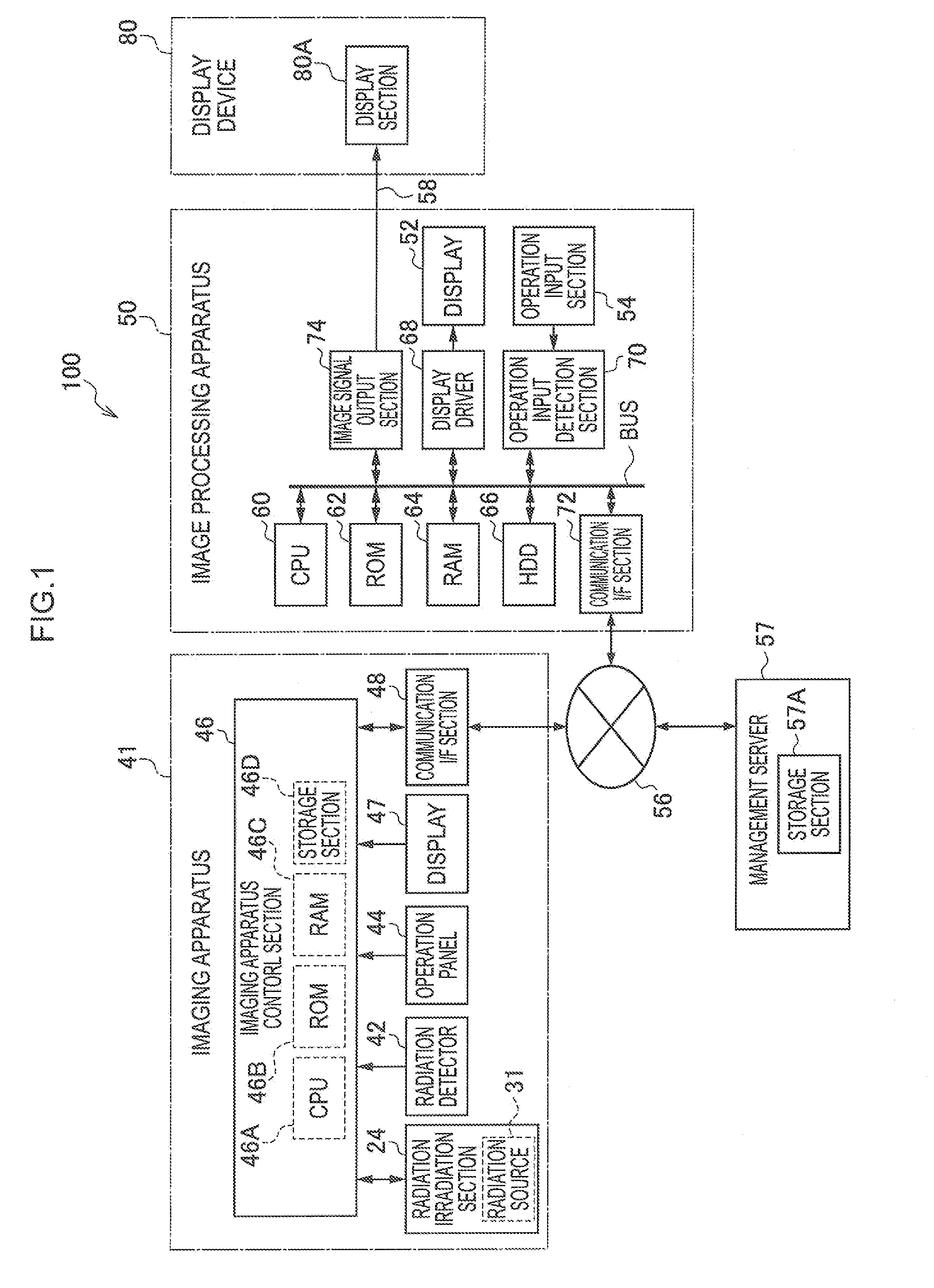
[0056]FIG. 1 is a block diagram illustrating a configuration of a radiographic imaging system 100 according to a first exemplary embodiment of the present invention. The radiographic imaging system 100 includes an imaging apparatus 41 that images radiographic images, an image processing apparatus 50 that performs image processing on image data expressing imaged radiographic images, and a display device 80 for displaying an image expressed by the image data that has been subjected to image processing.

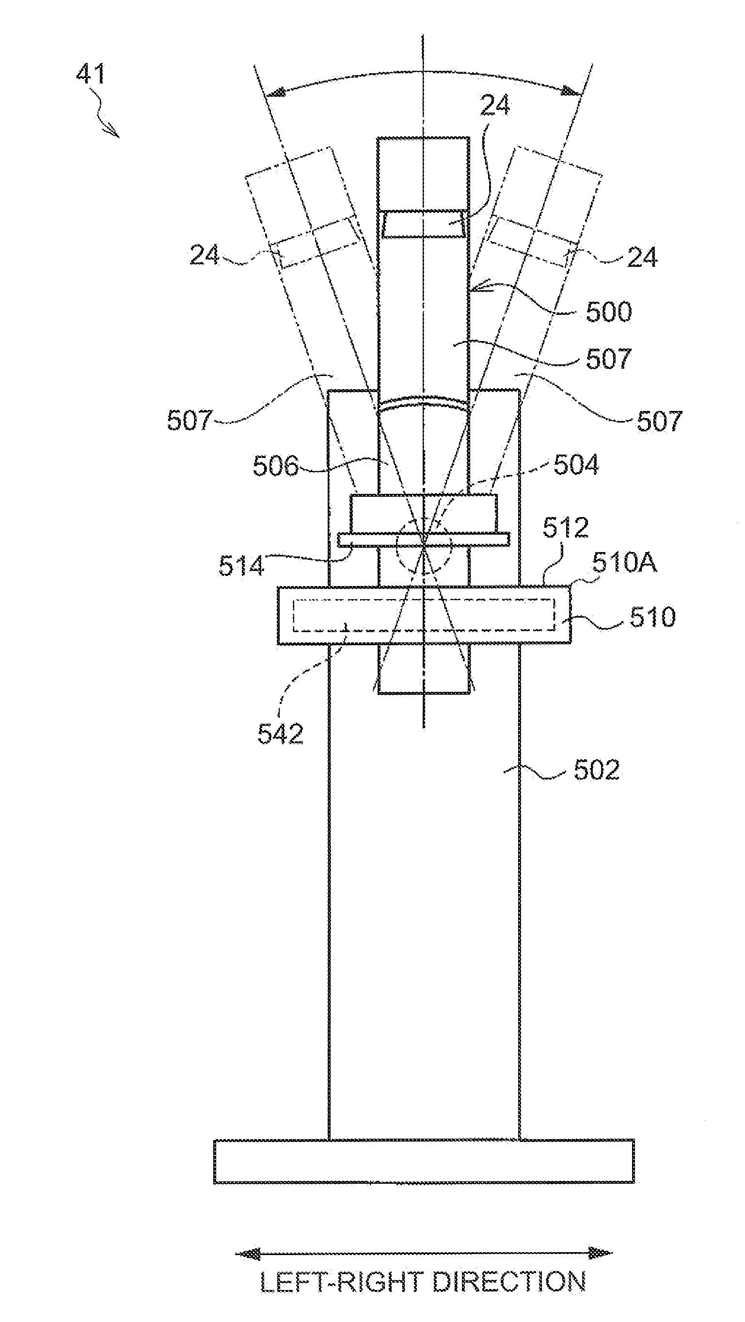
[0057]The imaging apparatus 41 includes a radiation irradiation section 24, a radiation detector 42 that detects a radiographic image, an operation panel 44 that is input with exposure conditions including data, such as, tube voltage, tube current, irradiation duration, imaging conditions, various operation data and various operation instructions, an imaging apparatus control section 46 that controls the operation of the apparatus overall, a display 47 that displays such displays as an o...

second exemplary embodiment

[0113]Explanation follows regarding a radiographic imaging system 100 according to a second exemplary embodiment of the present invention. Note that the radiographic imaging system 100 according to the second exemplary embodiment is similar to the radiographic imaging system 100 according to the first exemplary embodiment illustrated in FIG. 1, and so illustration and further explanation will be omitted.

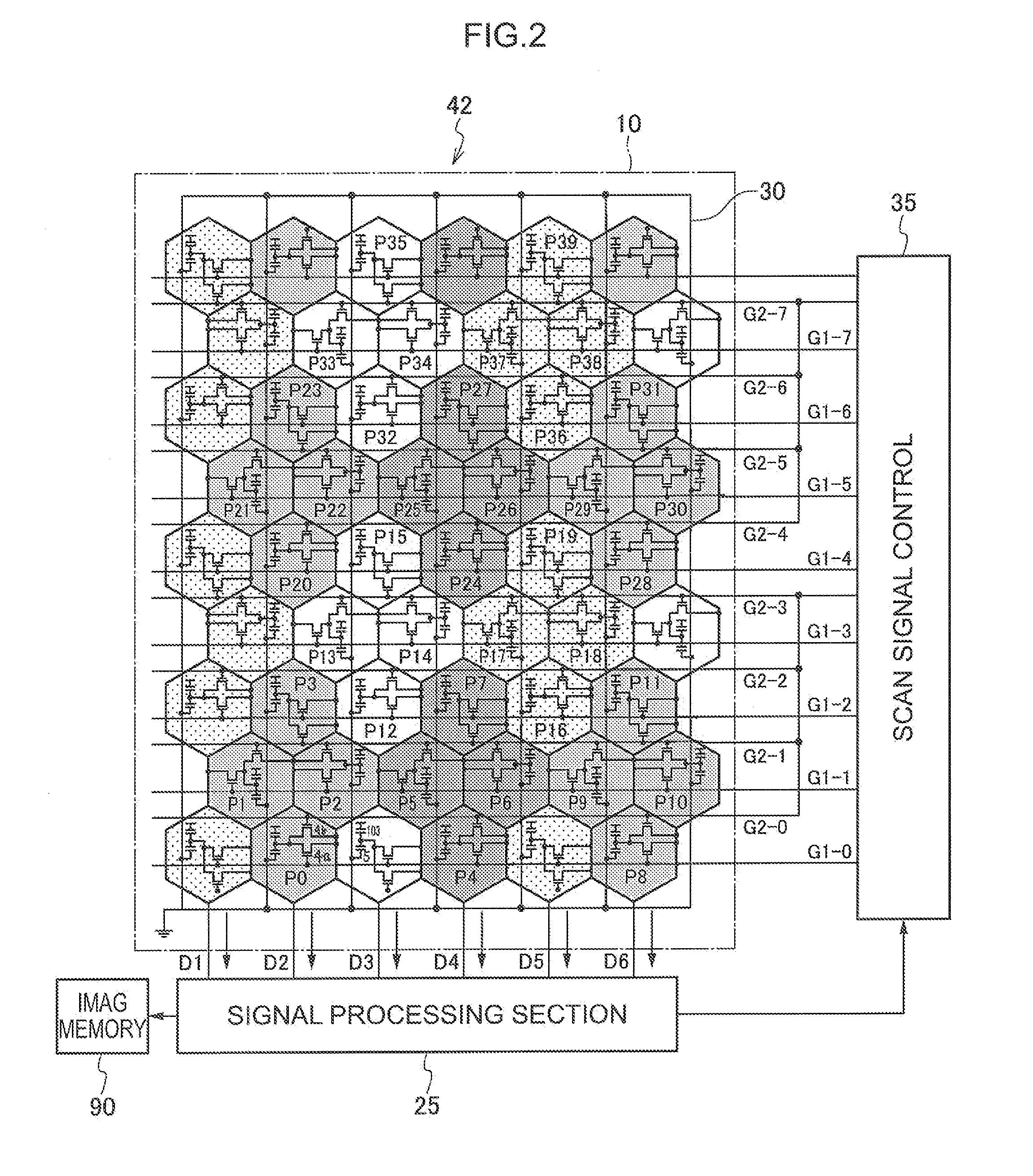
[0114]FIG. 6 illustrates an electrical configuration of a radiation detector 142 in an imaging apparatus 41 of a radiographic imaging system 100 according to the present exemplary embodiment. A radiation detection element 110 of a radiation detector 142 illustrated in FIG. 6 is configured with plural pixels 20 that have hexagonal shaped pixel regions arrayed adjacently in a two dimensional honeycomb pattern, such that the pixels 20 arrayed in a honeycomb pattern configure a rectangular shaped pixel region. Each of the pixels 20 is configured similarly to in the radiation detection el...

third exemplary embodiment

[0143]Explanation next follows regarding a radiographic imaging system 100 according to a third exemplary embodiment of the present invention. Note that the radiographic imaging system 100 according to the third exemplary embodiment is similar to the radiographic imaging system 100 according to the first exemplary embodiment illustrated in FIG. 1, and so illustration and further explanation will be omitted.

[0144]FIG. 8 illustrates an electrical configuration of a radiation detector 342 in an imaging apparatus 41 according to the third exemplary embodiment. A radiation detection element 310 of a radiation detector 342 illustrated in FIG. 8 is, similarly to the radiation detector 42 according to the first exemplary embodiment illustrated in FIG. 2, configured with plural pixels 20 that have hexagonal shaped pixel regions arrayed adjacently in a two dimensional honeycomb pattern, such that the pixels 20 arrayed in a honeycomb pattern configure a rectangular shaped pixel region.

[0145]Th...


PUM


Abstract

The present invention provides a radiographic image detector that may maintain even resolution in 6 directions before and after 3-pixel binning process or 4-pixel binning process. A radiation detector is disposed with plural pixels that have hexagonal shaped pixel regions, arrayed in a honeycomb pattern. Scan lines connected to TFT switches in each of the pixels are disposed one for each of the pixel rows. Grouped scan lines are also disposed one for each of the pixel rows for reading and combining 3 pixels or 4 pixels worth of charges at the same timing for plural pixel groups, each configured from 3 pixels or 4 pixels in a radiation detection element. ON signals are simultaneously sent by the grouped scanned lines to the TFT switches to perform 3-pixel binning or 4-pixel binning.

Description

CROSS-REFERENCE TO RELATED APPLICATION[0001]This application claims priority under 35 USC 119 from Japanese Patent Application No. 2011-282355, filed on Dec. 22, 2011, and Japanese Patent Application No. 2012-267524, filed on Dec. 6, 2012 the disclosure of which is incorporated by reference herein.BACKGROUND OF THE INVENTION[0002]1. Field of the Invention[0003]The present invention relates to a radiographic image detector, a radiographic imaging apparatus and a radiographic imaging system. The present invention particularly relates to a radiographic image detector, radiographic imaging apparatus and a radiographic imaging system for direct conversion of radiation into charges.[0004]2. Description of the Related Art[0005]Recently, radiographic image detection apparatuses that have being put into practice employ radiation detectors such as Flat Panel Detectors (FPDs) that have a X-ray-sensitive layer disposed above a Thin Film Transistor (TFT) active matrix substrate, and are capable ...

Claims


Application Information

Patent Timeline
IPC IPC(8): G01T1/16G01N23/04
CPCG01T1/16G01N23/046H04N5/32H04N5/347A61B6/502A61B6/032A61B6/0414A61B6/4233A61B6/025A61B6/4452H04N25/46
Inventor OKADA, YOSHIHIROIWAKIRI, NAOTOINOUE, TOMOKI
Owner FUJIFILM CORP
Why Eureka
Try Eureka