Electric vehicle driving system

a driving system and electric motor technology, applied in the direction of dynamo-electric components, cooling/ventilation arrangement, transportation and packaging, etc., can solve the problems of degrading the efficiency of electric motors due to the generated heat, and achieve the effect of reducing the size of the driving system, reducing the weight of the side cover, and reducing the cost of the electric motor

Active Publication Date: 2013-07-04
HONDA MOTOR CO LTD
View PDF2 Cites 22 Cited by
  • Summary
  • Abstract
  • Description
  • Claims
  • Application Information

AI Technical Summary

Benefits of technology

[0046]According to Claim 1, since the side cover is formed of a resin and is insulated from the electric motor, there is no need to provide an insulating distance or a dedicated insulating member for ensuring an insulating property between the side cover and the electric motor. Thus, the size of the driving system may be decreased and the cost thereof may be suppressed by decreasing the number of components. Since the side cover is formed of a resin, the weight of the side cover may be decreased. The heat generating portion of the electric motor may be efficiently cooled by supplying a lubricant from the oil path disposed near the electric motor, and the degradation in performance of the electric motor caused by a temperature increase may be suppressed.
[0047]According to Claims 2 and 3, the coil of the stator as the heat generating portion of the electric motor may be cooled by ejecting the lubricant toward the upper semicircular portion of the stator from the plural ejecting holes provided in the side cover in a pinpoint manner, and the size of the lubricant pump may be decreased by decreasing the amount of the lubricant used for cooling. The coil of the lower semicircular portion of the stator is cooled by the lubricant which droops due to the own weight.
[0048]According to Claim 4, the oil feeding path with a complex shape may be easily formed, and an effective cooling operation may be performed. Since a separate resin member is welded to the side cover, the rigidity of the side cover may be enhanced without providing plural ribs, and the weight may be further decreased.
[0049]According to Claims 5 and 7, the radio noise which may increase due to the resin side cover may be effectively suppressed.
[0050]According to Claim 6, the radio noise may be blocked in a portion which is close to the current flowing portion of the electric motor which is desired to be shielded.
[0051]According to Claims 8 to 10, the cooling performance for the coil of the stator using the lubricant may be improved.

Problems solved by technology

In the hybrid vehicle, heat is generated when the electric motor drives or is driven for regeneration, and the efficiency of the electric motor is degraded due to the generated heat.

Method used


Image

  • Electric vehicle driving system
  • Electric vehicle driving system
  • Electric vehicle driving system

Examples


Embodiment Construction

[0066]An embodiment of an electric vehicle driving system of the invention will be described by referring to the drawings. The drawings are seen as indicated by the reference signs.

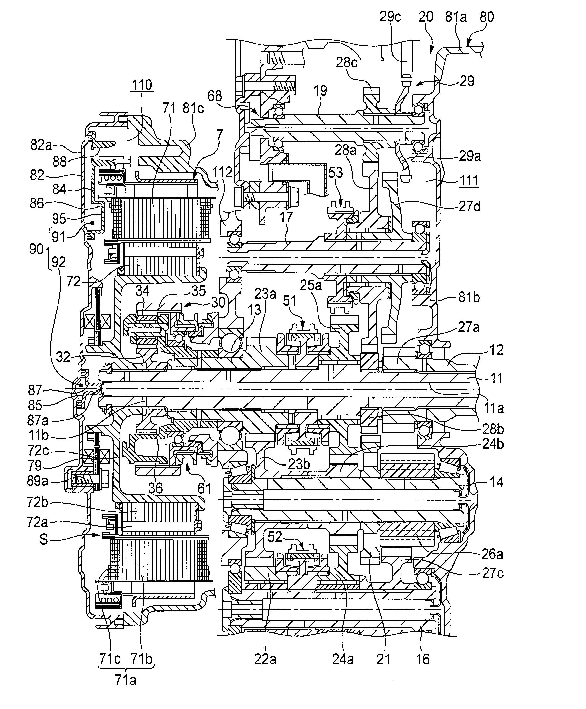
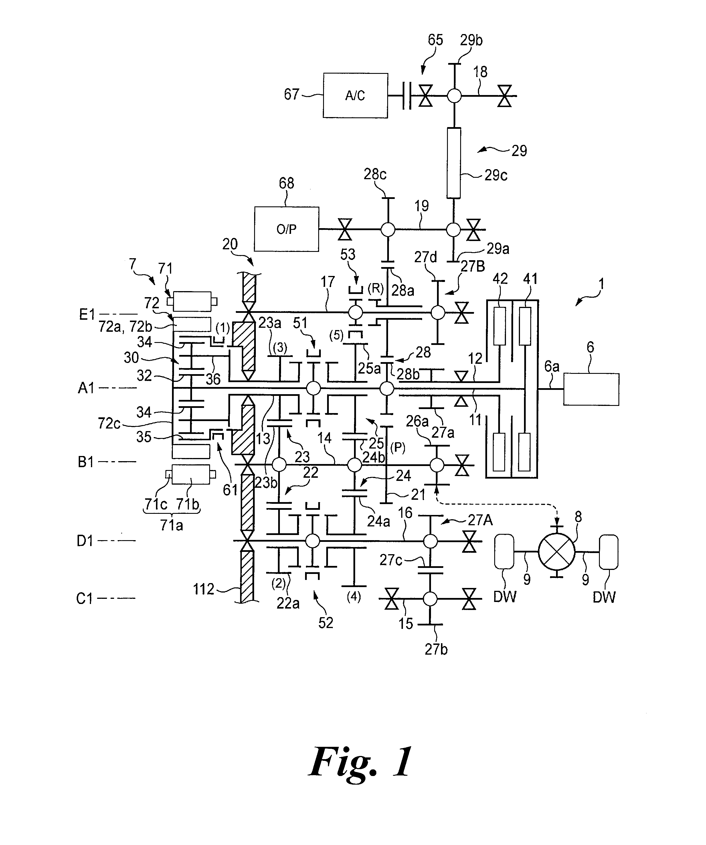
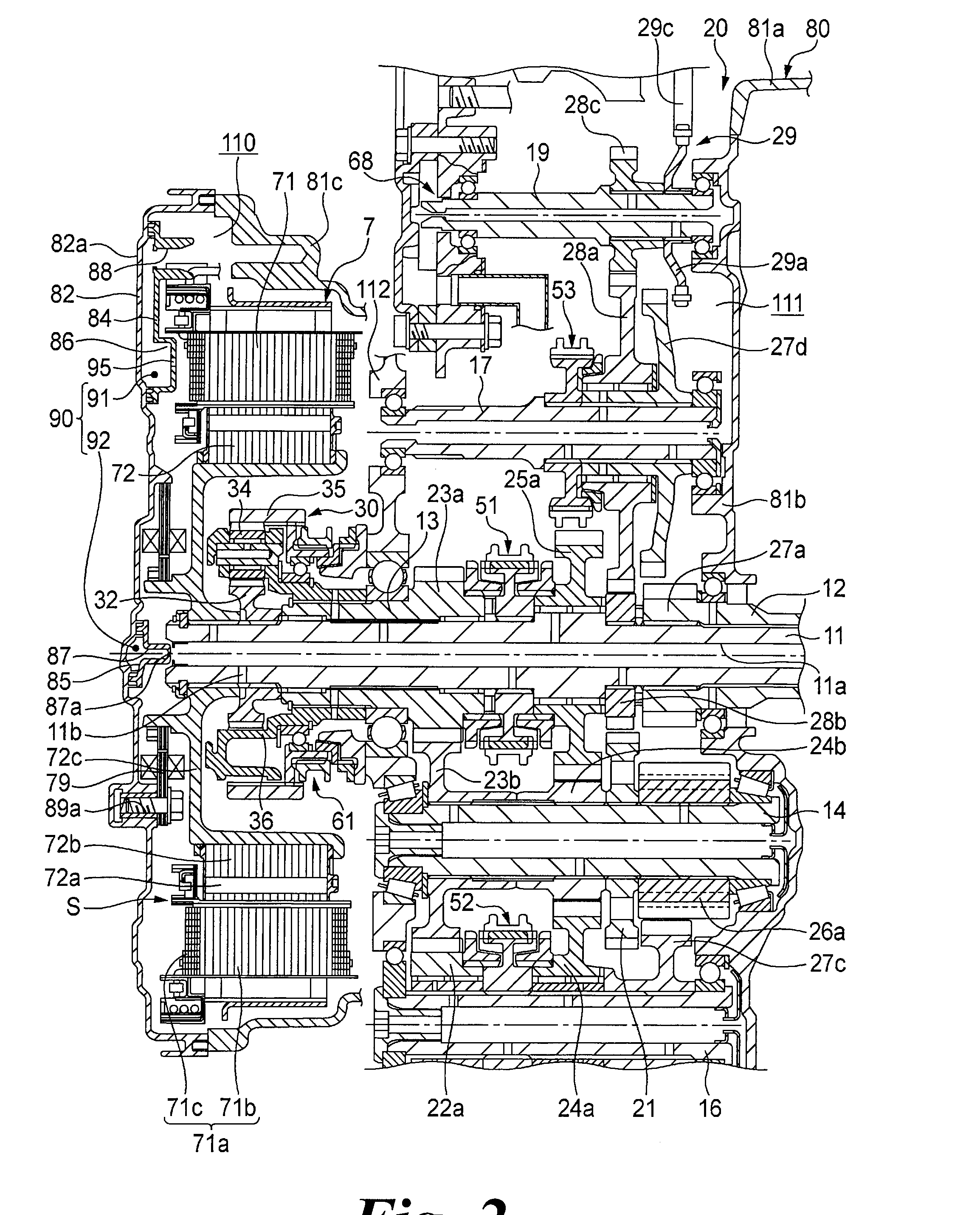
[0067]As shown in FIG. 1, a hybrid vehicle driving system 1 includes an internal combustion engine (engine) 6 which serves as a driving source, an electric motor 7, a speed changer (transmission) 20 which transmits power to driving wheels DW and DW (driving target portions), a planetary gear mechanism 30 which constitutes a part of the speed changer 20 and serves as a differential speed reducer, and a casing 80 which accommodates these components, thereby driving the driving wheels DW and DW through driving shafts 9 and 9 of a vehicle (not shown).

[0068]The casing 80 includes casings respectively formed of aluminum alloy, a clutch casing 81a which accommodates a first clutch 41 and a second clutch 42, a gear casing 81b which accommodates the speed changer 20, and a motor casing 81c which accommodates the e...


PUM


Abstract

A side cover 82 which covers a side surface portion of an electric motor 7 is formed of a resin, and a lubricant is ejected from plural ejecting holes 95 of an oil path 90 formed in the side cover 82 to a stator 71 of the electric motor 7 so as to cool the stator.

Description

TECHNICAL FIELD[0001]The present invention relates to an electric vehicle driving system, and particularly, to an electric vehicle driving system that cools an electric motor using a lubricant.BACKGROUND ART[0002]A known hybrid vehicle includes an internal combustion engine and an electric motor serving as a power source and appropriately converts the driving torques generated therefrom so as to be supplied to a drive-train depending on a traveling status. In the hybrid vehicle, heat is generated when the electric motor drives or is driven for regeneration, and the efficiency of the electric motor is degraded due to the generated heat. To handle such generated heat, the size of the electric motor is increased, or the electric motor is cooled by water-cooling using an installed water jacket or by oil-cooling using an oil pump for pressurizing a lubricant (cooling oil) of a transmission so as to be effected to the electric motor (for example, see PTL 1). PTL1 discloses the motor contr...

Claims


Application Information

Patent Timeline
Patent Type & Authority Applications(United States)
IPC IPC(8): H02K9/19H02K11/00H02K5/02
CPCH02K9/19Y02T10/641H02K11/022H02K11/0005H02K5/08H02K5/02Y02T10/64H02K11/0141
Inventor NAGAHAMA, TERUOKAWAI, NORIKAZUKOBAYASHI, HEISUKEFUJIMOTO, SHINJISAKAI, ATSUHIROMOGI, SEIICHIMITO, HIRONORI
Owner HONDA MOTOR CO LTD
Why Eureka
Try Eureka