Morphology engineering of conductive metallic nanoparticles capped with an organic coating

Active Publication Date: 2013-07-04
TECHNION RES & DEV FOUND LTD
View PDF3 Cites 14 Cited by
  • Summary
  • Abstract
  • Description
  • Claims
  • Application Information

AI Technical Summary

Benefits of technology

[0009]The present invention provides a method of controlling the sensitivity of monolayer-capped metallic nanoparticle (MCNP) chemiresistive sensors towards volatile organic compounds (VOCs) and/or water vapor by varying the morphology of MCNP films to comprise continuous

Problems solved by technology

This approach, however, incorporates synthesis challenges either of the molecular ligands or the MCNPs per se.
Likewise, a decrease (shrinking) in the interparticle separation within the continuous 3D morphology usually leads to a decrease in resistance.
A problem often encountered in the diagnosis

Method used


Image

  • Morphology engineering of conductive metallic nanoparticles capped with an organic coating
  • Morphology engineering of conductive metallic nanoparticles capped with an organic coating
  • Morphology engineering of conductive metallic nanoparticles capped with an organic coating

Examples


Example

Example 1

Characterization of MCNP Films

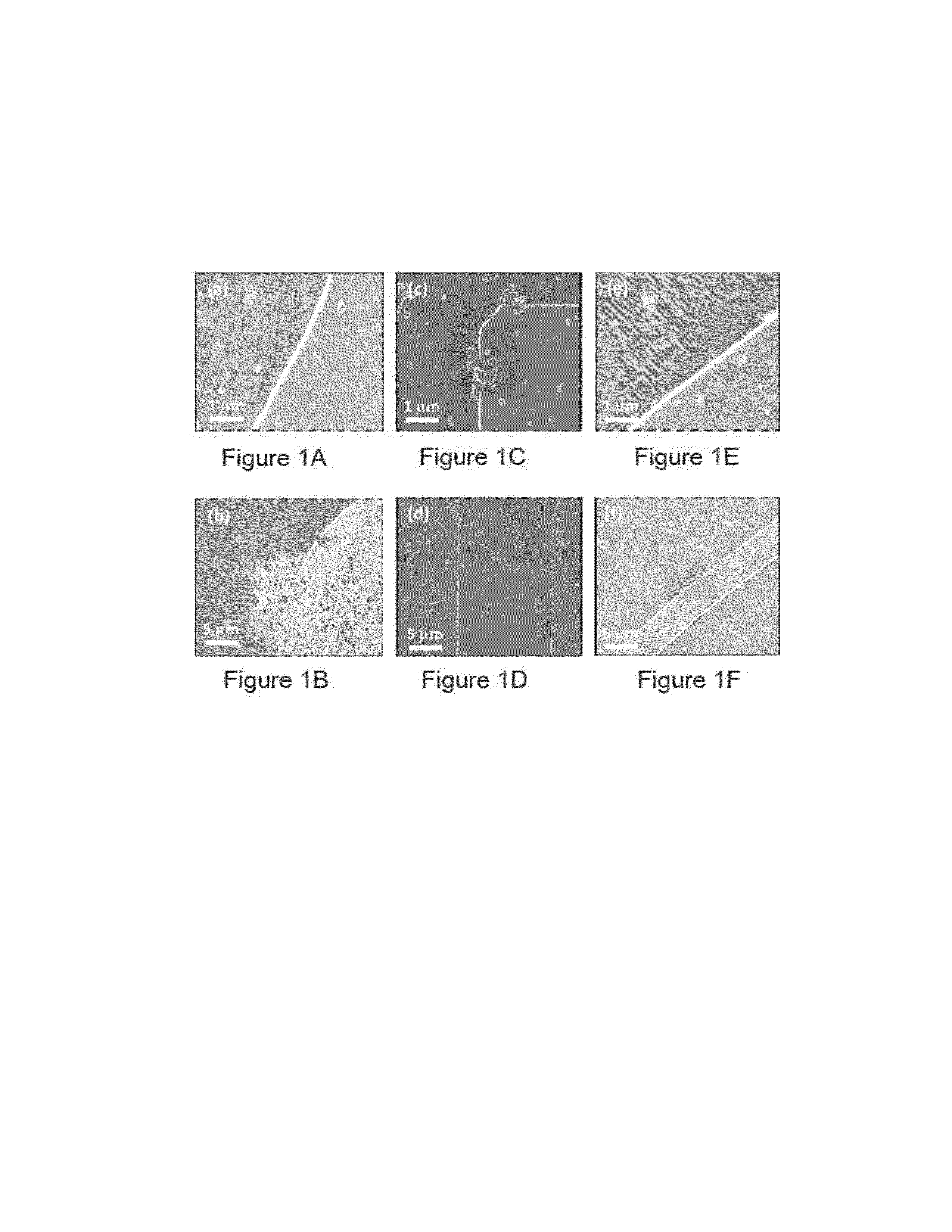
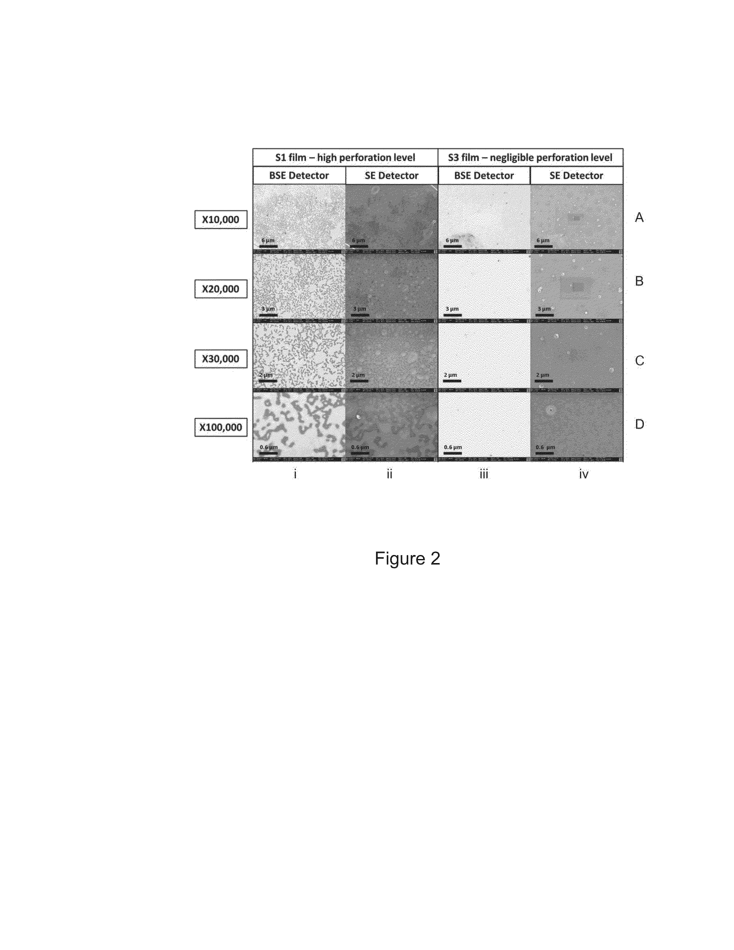
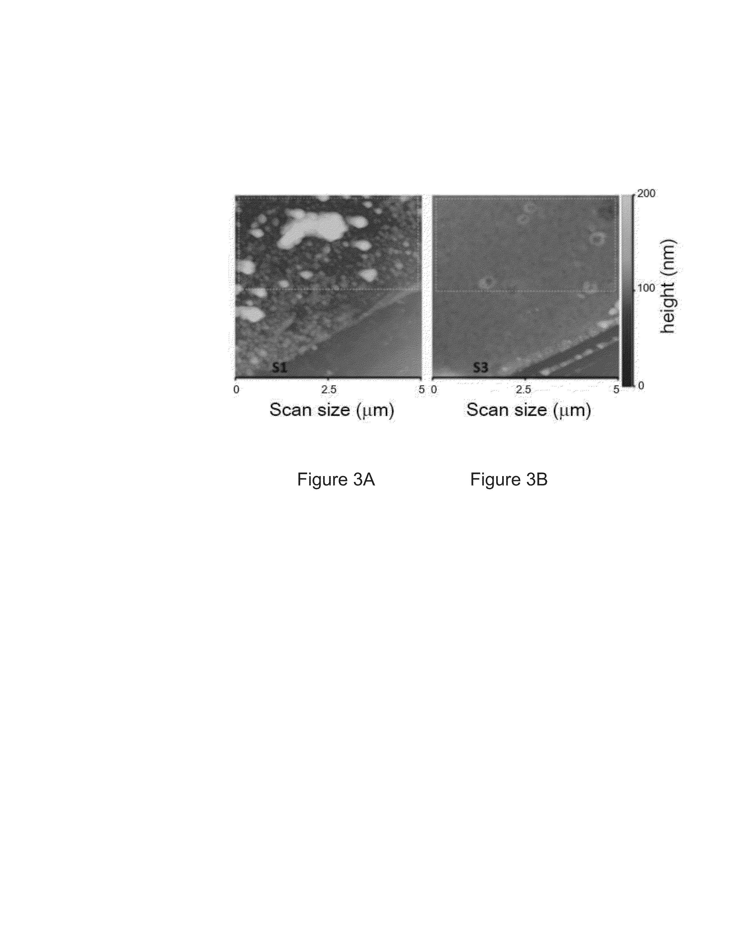
[0094]Aliquots of nitro-4-trifluoro-methylbenzenethiol-capped gold nanoparticle (NTMBT-AuNP) solution were drop-cast on interdigitated electrodes under various humidity conditions: 16% RH (S1), 31% RH (S2) and 54% RTI (5). Similar baseline resistance, electrical properties and responses to VOCs and water were obtained for ˜90% of the sensors produced in each humidity condition. The varying Relative Humidity (RH) conditions led to the formation of high baseline resistances for representative sensors S1 and S2 (˜18 MΩ) and to the formation of relatively low baseline resistance for S3 (˜5 MΩ), FIGS. 1A-1F present field emission high resolution scanning electron microscopy (FE-HRSEM) images of the S1-S3 films. As seen in these figures, drop-casting under different RH conditions controlled the morphology of the NTMBT-AuNP films. The films deposited under a high humidity level (54% RH) resulted in more uniform layers with less aggregates. In contras...

Example

Example 2

Response to VOCs and Water Vapor

[0097]S1-S3 sensors were exposed to various concentrations of decane, 2-ethylhexanol (with constant background humidity level of ˜5%) and water, FIGS. 4A-4C show the responses obtained from triplicates of S1, S2, and S3, prepared in different casting cycles, to different humidity levels. Rend is the resistance at the end of the sensing signal and ΔR is the Rend-corrected resistance change upon exposure of the sensor to the analyte. The notation Cycle ij describes the sensor's type, via the numerical digit (i=1, 2 or 3), and the casting cycle, via the alphabetical capital letters (j=A, B, or C). Evidently, the results show that the variations obtained within a specific batch production (i.e., under a specific RH condition) are much smaller than variations in responses from different batch productions (i.e., production under different RH conditions). FIGS. 5A-5D show the resistance responses, ΔR / Rend, of the sensors upon exposure to analytes. ...

Example

Example 3

Modeling and Sensing Relative Humidity Conditions

[0099]In order to study the response of sensors comprising discontinuous regions to water vapor, the normalized responses, ΔR / Rbase of sensors of NTMBT-AuNP and ETP-AuNP vs. humidity (FIGS. 6A-6B) were modeled to produce a linear equation which represents the change in resistance as a function of relative humidity (without including relative humidity levels which produce a drop in resistance due to the accumulation of ions at the vicinity of the oppositely charged electrodes). A blind test analysis of 20% of the samples was performed using S4 and S5 sensors. The accuracy of the blind test was determined as 86% for both sensors (Table 2). Thus, the sensors of the present invention provide a reliable measurement of the relative humidity of a sample by measuring the change in resistance from baseline resistance upon exposure to the sample. An increase in accuracy can further be achieved through post-processing analysis (e.g. in...


PUM


Abstract

The present invention is directed to a sensor having continuous and discontinuous regions of conductive metallic nanoparticles capped with an organic coating which enables the detection of volatile organic compounds and/or water vapor.

Description

FIELD OF THE INVENTION[0001]The present invention is directed to the detection of volatile organic compounds and water vapor using a sensor comprising continuous and discontinuous regions of conductive metallic nanoparticles capped with an organic coating, wherein the continuous and discontinuous regions differentially detect volatile organic compounds and water vapor.BACKGROUND OF THE INVENTION[0002]Monolayer-capped metallic nanoparticles (MCNPs) have attracted significant attention during the past two decades, due to their unique bulk and surface properties (Mokari, Nano Rev. 2011, 2, 5983; Tisch & Haick, MRS Bull. 2010, 35(1), 797; Tisch & Haick, Rev. Chem. Eng. 2010, 26, 171; Haick, J. Phys. D 2007, 40, 7173; Daniel & Astruc. Chem. Rev. 2004, 104, 293). Sensors based on MCNP films are of special interest, mainly due to their controllable selectivity, high sensitivity, low detection limits, fast response and recovery times, small size, low-output impedance and easy integration in...

Claims


Application Information

Patent Timeline
IPC IPC(8): G01N30/00
CPCG01N30/00G01N27/121B82Y15/00G01N33/0031G01N27/127G01N27/223
Inventor HAICK, HOSSAMSEGEV-BAR, MEITALSHUSTER, GREGORYGLIKSMAN, SADI
Owner TECHNION RES & DEV FOUND LTD
Why Eureka
Try Eureka