Context-sensitive flow interrupter and drainage outflow optimization system

a technology of interrupter and interrupter, which is applied in gravity drainage system, medical science, other medical devices, etc., can solve the problems of urinary catheters contributing to urinary tract infections, preventing 100% of urine from going backwards, and infection and patient discomfor

Active Publication Date: 2013-07-04
UNIV OF FLORIDA RES FOUNDATION INC
View PDF3 Cites 21 Cited by
  • Summary
  • Abstract
  • Description
  • Claims
  • Application Information

AI Technical Summary

Benefits of technology

[0023]Embodiments of the invention provide methods and devices for improved drainage systems. As described herein, methods and devices are provided that can aid in controlling pressure within drainage

Problems solved by technology

A primary risk with urinary catheters is their contribution to urinary tract infections.
However, when transporting a patient, the drainage collection bag is often placed on the patient's abdomen or on the transport gurney instead of at the proper lower hanging location.
A problem with placing the collection bag on the belly of the patient is that when the bag is higher than the bladder, it is possible for urine in the bag or tubing to flow back to the patient.
This backflow of urine can cause infection and patient discomfort.
Although backflow is a recognized problem, on any drain bag or urine meter bag available on the market, if the bag is squeezed, held upside-down, or held above the level of the patient's bladder, it will not stop 100% of urine from going backwards.
Unfortunately, one way-valves (non-return or non-reflux valves) cannot be used to prevent back-flow of urine because the CDC Guidelines for Prevention of Catheter-Associate

Method used


Image

  • Context-sensitive flow interrupter and drainage outflow optimization system
  • Context-sensitive flow interrupter and drainage outflow optimization system
  • Context-sensitive flow interrupter and drainage outflow optimization system

Examples


embodiment 1

[0137]2. The apparatus , wherein the flow interrupter comprises a clamp, stopcock, or cuff.

[0138]3. The apparatus according to embodiment 1, wherein the flow interrupter comprises a normally closed clamp capable of bringing a first portion of an interior wall of a drainage tube in contact with a second portion of the interior wall of the drainage tube such that fluid is inhibited from passing through the flexible drainage tube, wherein interacting the normally closed clamp with the holder portion causes the normally closed clamp to open.

embodiment 3

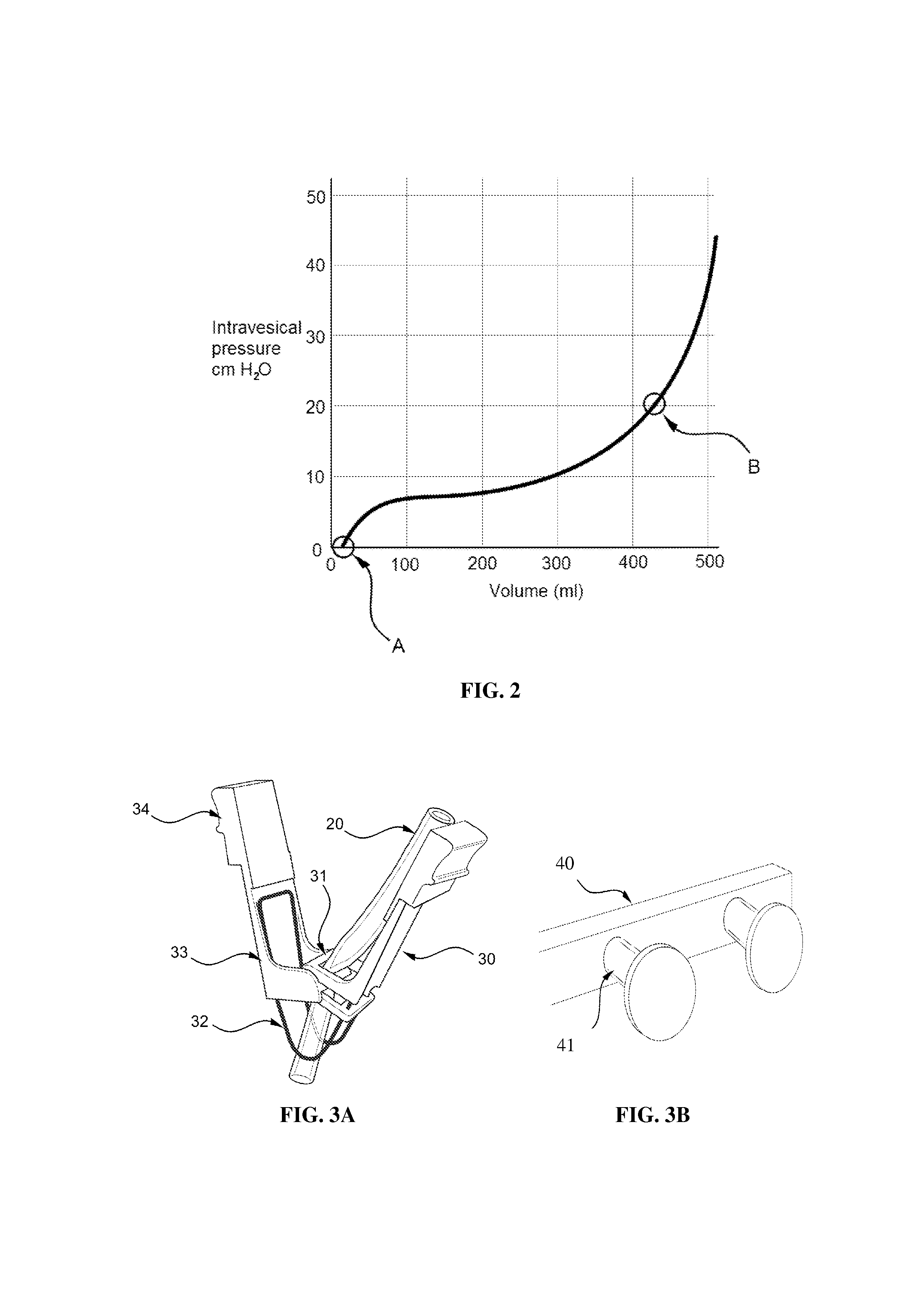
[0139]4. The apparatus , wherein the normally closed clamp comprises a jaw-opening spring clamp having two arms extending from the spring clamp and the holder portion can comprise one or more brackets or rods defining a receptacle for the jaw-opening spring clamp, the receptacle having a diameter or opposing sidewall spacing smaller than a distance between the distal ends of the two arms, wherein insertion of the jaw-opening spring clamp into the receptacle causes the distance between the distal ends of the two arms to decrease, thereby opening the jaw-opening spring clamp.

[0140]5. The apparatus according to embodiment 3, wherein the normally closed clamp comprises a resilient deformable material on or within the section of the drainage tube, wherein the resilient deformable material causes the section of the flexible drainage tube to be in a collapsed position until interacted with the holder portion.

[0141]6. The apparatus according to embodiment 1, wherein the holder portion is co...

embodiment 7

[0143]8. The apparatus , wherein the mechanical template comprises a peg, groove, or bracket assembly.

[0144]9. The apparatus according to embodiment 7, further comprising a drainage collection bag holder affixed at one end of the mechanical template for hooking the drainage collection receptacle thereto.

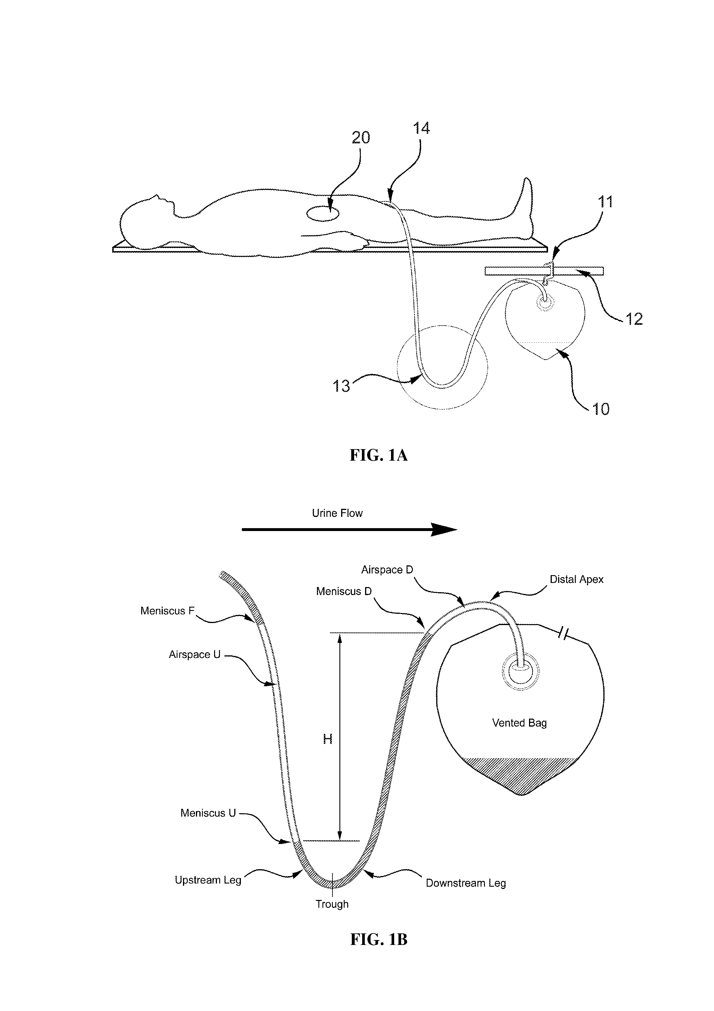
[0145]10. A drainage assembly comprising: a drainage tube having a pressure equalizing vent, and a drainage collection bag connected to the drainage tube.


PUM


Abstract

Embodiments of the invention provide methods and devices for improved drainage systems and tubing. In one embodiment, a context-sensitive flow interrupter is provided that inhibits or facilitates flow of fluid when engaged with a mating holder. In another embodiment, outflow is optimized through control of the pressure in gas pockets in a tube, drainage tube or assembly. In one such embodiment, gas pockets are vented to inhibit excessive back-pressure or suction on an organ, vessel or cavity being drained. In another such embodiment, loops in the tubes are avoided by using a mechanical template in the form of a groove or peg assembly to thread the slack in the drainage tube to generate a monotonic gradient. In another embodiment, such as for active drainage systems, a bypass channel is provided that allows an applied vacuum to go around an obstruction created by the collection of fluid in an undrained dependent loop.

Description

CROSS-REFERENCE TO RELATED APPLICATION[0001]This application claims the benefit of U.S. Provisional Application Ser. No. 61 / 381,266, filed Sep. 9, 2010, which is hereby incorporated by reference in its entirety, including all figures, tables and drawings.BACKGROUND OF THE INVENTION[0002]Current medical practice requires some body cavities, organs (e.g., the bladder or kidney), spaces (e.g., the pleural space), or wounds of patients to be drained of fluid whether in the liquid form (e.g., urine or blood) or gaseous form (e.g., air, gas) or a gas / liquid mixture (e.g., frothy exudate). For example, current medical practice includes draining blood in a hemothorax and air, gas, or frothy exudate from a pneumothorax.[0003]Examples of urine drainage include urinary catheters inserted via the urethra, nephrostomy tubes, and suprapubic catheters. Nephrostomy tubes are inserted directly in the calyx of the kidney through the patient's back to drain urine from the kidneys. A suprapubic cathete...

Claims


Application Information

Patent Timeline
IPC IPC(8): A61M25/00
CPCA61M1/0021A61M39/08A61M25/0017A61M39/284A61M39/28A61M1/70A61M1/83
Inventor LAMPOTANG, SAMSUNGRAVENSTEIN, NIKOLAUSSCHWAB, WILHELM K.LIZDAS, DAVID E.ENNEKING, FRANCESCA K.
Owner UNIV OF FLORIDA RES FOUNDATION INC
Why Eureka
Try Eureka