Housing assembly with reed switch and magnet

a technology of reed switch and magnet, which is applied in the direction of engine-driven generators, electric devices, transportation and packaging, etc., can solve the problems of reducing the service or repair space within the engine compartment, unable to achieve the design performance characteristics of electric vehicles, and unable to physically access electric power lines by workers servicing vehicles, so as to reduce the manufacturing cost of time and materials and make the service or repair operation safer.

Inactive Publication Date: 2013-07-11
REMY TECHNOLOGIES LLC
View PDF1 Cites 10 Cited by
  • Summary
  • Abstract
  • Description
  • Claims
  • Application Information

AI Technical Summary

Benefits of technology

[0007]The subject invention provides a vehicular subsystem and electric machine that simplify and make safer a servicing or repair operation being performed near high voltage lines of an electric vehicle. Similarly, a manufacturing cost for time and materials is reduced.

Problems solved by technology

In many applications, the designed performance characteristics of an electric vehicle can only be achieved by supplying dangerous high voltages to a drive system.
For this and other configurations, a worker servicing the vehicle may have difficulty physically accessing the electric power lines, for example within a small engine compartment of a passenger car.
The wiring to the limit switch may necessitate the use of an additional connector which further reduces available servicing space within an engine compartment.
Such limit switches and associated installations are costly, heavy, bulky, difficult to install / remove, and are subject to contamination, heat, vibration, and related reliability issues.
With respect to reducing a danger of injury to persons working near dangerous high voltage(s) of an electric vehicle, conventional interlock devices and systems are not optimized for service, repair, or manufacturing of electric vehicles.

Method used


Image

  • Housing assembly with reed switch and magnet
  • Housing assembly with reed switch and magnet
  • Housing assembly with reed switch and magnet

Examples


Embodiment Construction

[0029]The embodiments described below are not intended to be exhaustive or to limit the invention to the precise forms disclosed in the following detailed description. Rather, the embodiments are chosen and described so that others skilled in the art may appreciate and understand the principles and practices of the present invention.

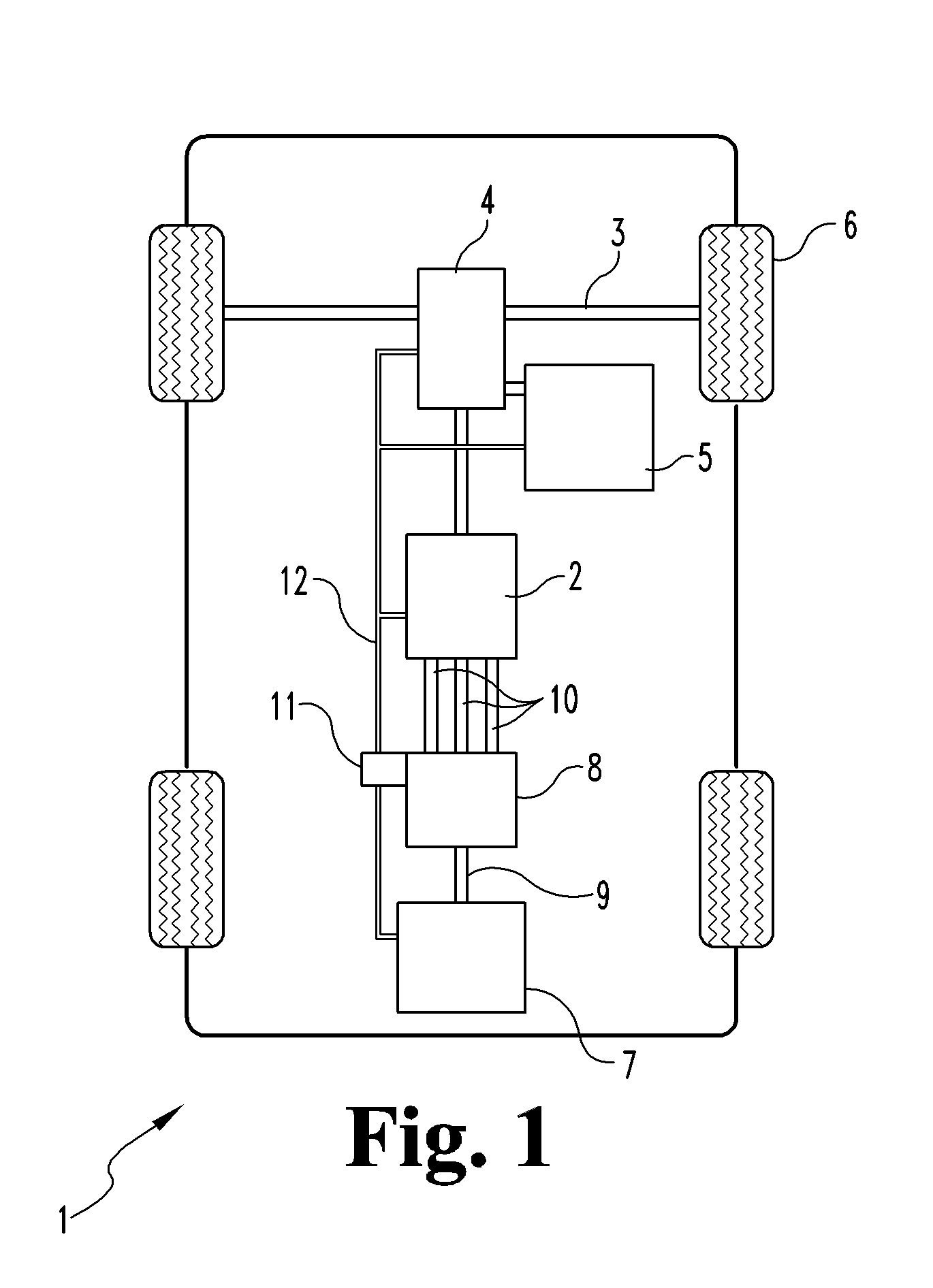
[0030]FIG. 1 shows a schematic view of an exemplary vehicle1 with an electric machine 2 coupled to a drive axle 3 via transmission 4. An internal combustion type motor is also coupled to drive axle 3 via transmission 4. It is noted that, respecting various embodiments, vehicle 1 may be designed and built without transmission 4 (e.g., direct drive) and / or internal combustion type motor 5 (e.g., all-electric). When vehicle 1 is a hybrid, power is provided to drive axle 3 by electric machine 2, internal combustion motor 5, or some combination of the two. As used herein, an “electric vehicle” refers to any vehicle that includes an electric machine as part of...


PUM


Abstract

An electric machine and vehicular subsystem, apparatus includes a connection disposed within a housing and connecting a high voltage line with the electric machine. A controller controls the coupling of a power source to the high voltage line. A reed switch is positioned within the housing proximate the high voltage line connection. A member is removably mounted on the housing and structured so that removal of the member is necessary to gain access to the high voltage line connection, the member having a magnet. At least one low voltage communication line extends from the reed switch to the controller. Removal of the member from the housing opens the reed switch. Mounting of the member to the housing closes the reed switch. The controller terminates the providing of electric power to the high voltage line when the member is removed from the housing.

Description

BACKGROUND OF THE INVENTION[0001]The invention relates generally to vehicular electrical systems and, more particularly, to an apparatus and system for reducing a danger of contact with high voltage present in a vehicle.[0002]Electric vehicles are generally propelled by one or more electric or traction motors powered by electricity, alone or in combination with non-electric propulsion, for example, motive force provided by an internal combustion engine. A source of such electric power may be stored electricity, for example, from a battery bank, electricity generated within the vehicle, and / or electricity received from an external source, such as a trolley in electrical communication with overhead power lines.[0003]In many applications, the designed performance characteristics of an electric vehicle can only be achieved by supplying dangerous high voltages to a drive system. Direct current (DC) voltage may be directly supplied to a DC motor or it may be converted to alternating curre...

Claims


Application Information

Patent Timeline
Patent Type & Authority Applications(United States)
IPC IPC(8): B60L1/00H02K21/02
CPCH02K3/50H02K5/06H02K5/225B60L3/04B60L3/0061Y02T10/641B60L2200/22Y02T10/7077Y02T90/16Y02T10/70B60L11/14B60L50/16Y02T10/64Y02T10/7072
Inventor CHAMBERLIN, BRADLEY D.HAMER, COLINRAMEY, CARY
Owner REMY TECHNOLOGIES LLC
Why Eureka
Try Eureka