Adaptive optical devices with controllable focal power and aspheric shape

a technology of adaptive optical devices and focal power, applied in the field of liquid lens, can solve the problems of difficult to maintain a stable interface for clear apertures greater than about 5-mm diameter, remote location of pressurized fluid sources, and slow response time, so as to reduce optical aberration, limit the ability to control optical properties, and reduce optical aberration.

Active Publication Date: 2013-07-11
HOLOCHIP
View PDF3 Cites 86 Cited by
  • Summary
  • Abstract
  • Description
  • Claims
  • Application Information

AI Technical Summary

Benefits of technology

[0013]Yet another inherent disadvantage of typical fluidic lenses is that the shape profile and resulting optical properties of the lens are substantially governed by the tensile elastic properties of the membrane (e.g., Young's modulus, thickness, and amount of pre-tensioning) and fluid pressure. In conventional optics, it is often desirable for the surface of a lens to have a spherical, or prescribed aspheric, profile. However, in the case of fluidic lenses, the highly compliant nature of the membrane generally results in a strong nonlinear dependence of the membrane profile on fluid pressure. Thus, instead of maintaining a spherical profile independent of fluid pressure (i.e., fluid pressure only affecting the radius of curvature), the membrane profile of the fluidic lens may deviate significantly from spherical, with the amount of deviation being dependent on fluid pressure. Such complex dependencies can severely limit the ability to control the optical properties (such as aberrations, the conic constant and other optical effects) of fluidic lenses.
[0014]More recently, another co-pending application Ser. No. 12/706,637 (“VARIABLE-FOCAL-LENGTH FLUIDIC LENS WITH REDUCED OPTICAL ABERRATION”, to Batchko et al.) taught means by which the aforementioned limitations could be largely overcome. A key element in overcoming these limitations was the use of membranes constructed from intrinsically stiff materials, such as glass or optical plastics. In such stiff materials the nature of the deformation is substantially a bending strain, whereas in the case of compliant membranes (such as those composed of elastomer films) the deformation is substantially an elastic strain. In such membranes that deform by bend

Problems solved by technology

Although the electrowetting approach yields a conveniently compact system with low power requirements and fast response, it is difficult to maintain a stable interface for clear apertures greater than about 5-mm diameter.
While this device overcomes many limitations typical of other LC lenses, such as strong astigmatism, distortion and light scattering, it suffers from a slow response time.
That system still suffers from the disadvantage that the pressurized fluid source is located remotely from the compartment.
This makes the form-factor of the whole system inconvenient.
While fluidic lenses are capable of overcoming many problems associated with liquid lenses, such as slow response time, instability of large apertures and optical losses, certain limitations remain.
However, such low elastic modulus may cause the lens to be susceptible to disturbances, such as instabilities in focus and tilt due to forces of acceleration, and aberrations, such as coma, which may be due to gravitational forces.
Nevertheless, is some instances (for example, lenses with small f/#'s or large apertures) coma and other gravity-induced aberrations persist.
Another inherent disadvantage of many low-elastic modulus membrane materials (for example, polydimethylsiloxane or PDMS) is their permeability, or inability to effectively block the passage of some gases and fluids.
Such permeability may result in air bubbles developing in, or fluid leaking out of, the fluidic lens.
These effects can diminish the durability, lifetime, optical quality, dynamic range and other performance properti

Method used


Image

  • Adaptive optical devices with controllable focal power and aspheric shape
  • Adaptive optical devices with controllable focal power and aspheric shape
  • Adaptive optical devices with controllable focal power and aspheric shape

Examples


embodiment

Preferred Embodiment

Ring-on-Ring Load and Stiff Optical Surface

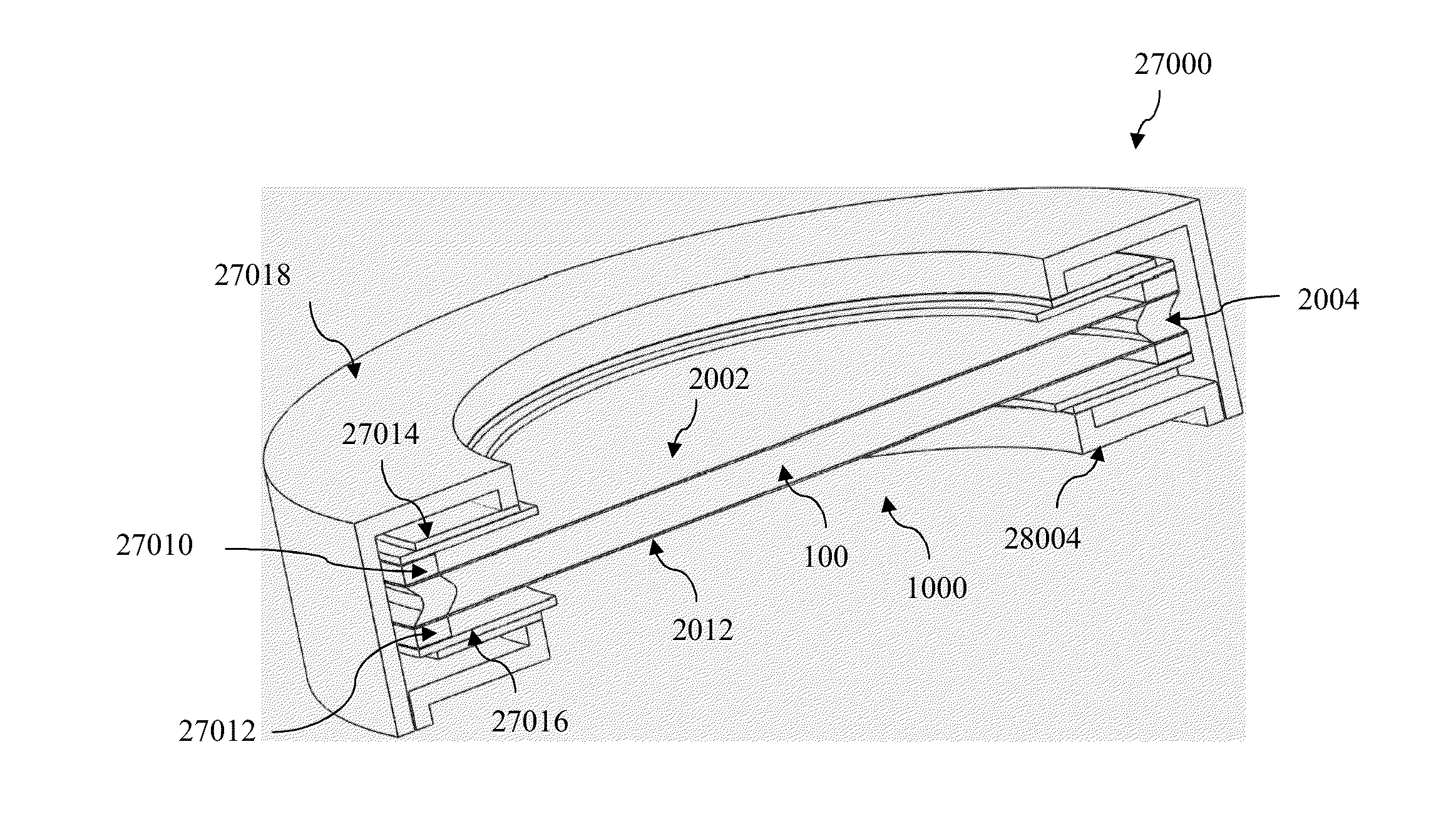
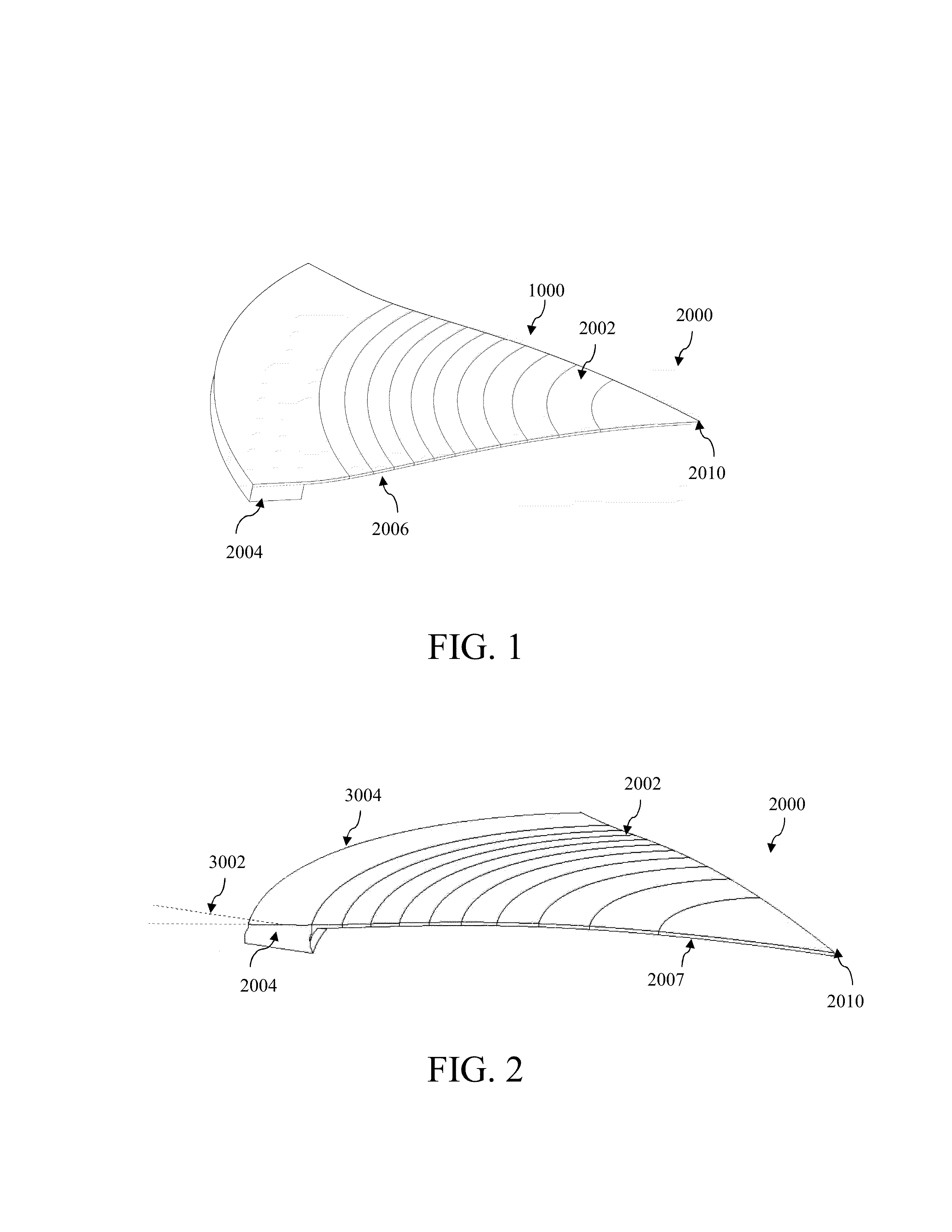
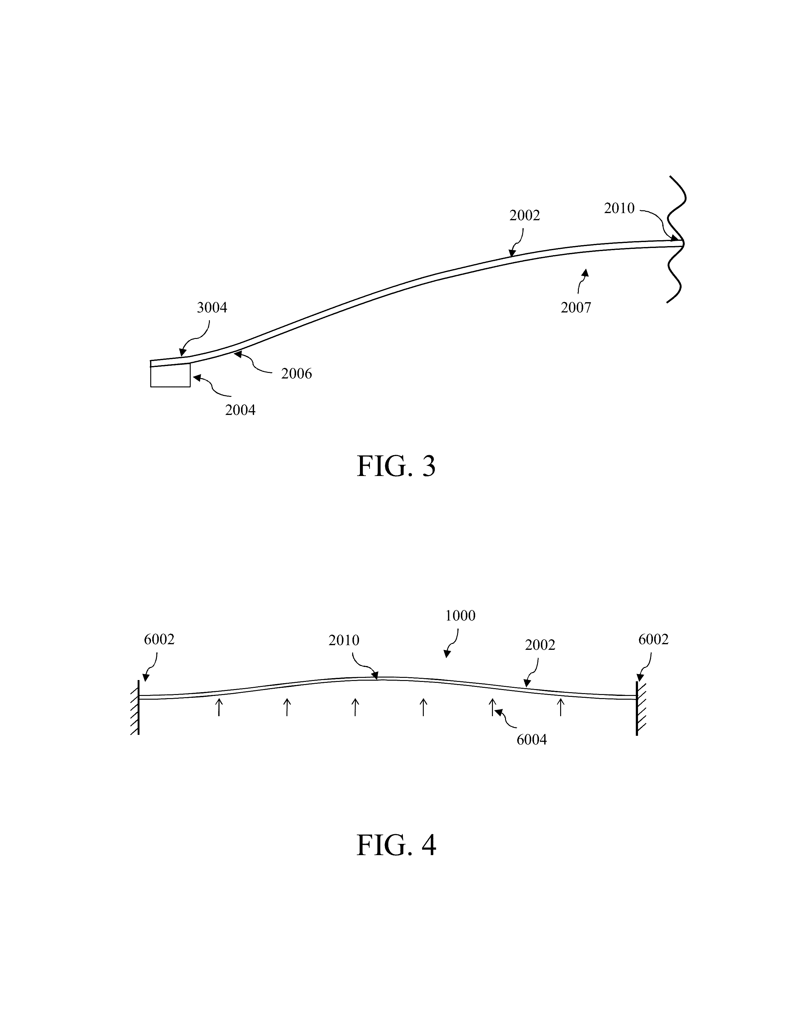
[0137]In a preferred embodiment, spherical curvature may be maintained in the clear aperture region of the optical surface throughout its states of deflection by the use of a stiff optical surface and concentrated concentric ring-on-ring (or “double-ring”) applied load. In one example of such a configuration, a compartment may be bounded by a first optical surface and a second optical surface. One or more of first and second optical surfaces may be capable of deflection by bending. Further, first and second optical surfaces may be circular-disk shaped and have substantially the same edge radius. A first ring-shaped support (first support) may be configured with a first support radius substantially equal to, or slightly smaller than the edge radius. The first support may be fastened to first and second optical surfaces and may form a seal. First support may be at least partially compliant and configured to allow first and...


PUM


Abstract

A fluidic lens may include an optical surface configured for deflection dominated by bending stress. An adjustable concentric load may be applied to the optical surface to cause a clear aperture region of the optical surface to deflect with generally spherical curvature. Adjusting the concentric load controls the radius of curvature. An adjustable uniformly-distributed load may be applied to the optical surface by fluid pressure that causes the clear aperture region to deflect with an aspheric shape. Adjusting the pressure controls the asphericity of curvature. First and second fluids having similar densities and different refractive indexes may be disposed on either side of a deflectable optical surface to help balance gravitational loading on either side of the optical surface, thereby reducing gravity-associated aberrations.

Description

CROSS-REFERENCE TO RELATED APPLICATION[0001]This application is a continuation-in-part of commonly assigned U.S. patent application Ser. No. 13 / 301,492, to Robert G. Batchko et al., entitled “FLUIDIC LENS WITH REDUCED OPTICAL ABERRATION”, filed Nov. 21, 2011, the entire contents of which are incorporated herein by reference. U.S. patent application Ser. No. 13 / 301,492 is a continuation of and claims the priority benefit of commonly assigned U.S. patent application Ser. No. 12 / 706,637, to Robert G. Batchko et al., entitled “FLUIDIC LENS WITH REDUCED OPTICAL ABERRATION”, filed Feb. 16, 2010, now U.S. Pat. No. 8,064,132, the entire contents of which are incorporated herein by reference.[0002]This application is a continuation-in-part of and claims the priority benefit of commonly assigned U.S. patent application Ser. No. 12 / 706,637, to Robert G. Batchko et al., entitled “FLUIDIC LENS WITH REDUCED OPTICAL ABERRATION”, filed Feb. 16, 2010, now U.S. Pat. No. 8,064,132, the entire contents...

Claims


Application Information

Patent Timeline
IPC IPC(8): G02B3/12
CPCG02B3/12G02B26/005G02B3/14
Inventor BATCHKO, ROBERT G.SZILAGYI, ANDREIROBINSON, SAMUEL T.
Owner HOLOCHIP
Why Eureka
Try Eureka