Adaptive limitation of standby mode to enhance fuel cell system life

Active Publication Date: 2013-07-11
GM GLOBAL TECH OPERATIONS LLC
View PDF1 Cites 8 Cited by
  • Summary
  • Abstract
  • Description
  • Claims
  • Application Information

AI Technical Summary

Benefits of technology

[0015]In accordance with the teachings of the present invention, a system and method are disclosed for reducing the frequency of stack stand-by mode events, if necessary, as a fuel cell stack ages and experiences lower performance. The method determines an irreversible voltage loss of the fuel cell stack at predetermined time intervals and determines a stack voltage degradation variable based on the irreversible voltage loss. The method also determines if the stack voltage degradation variable indicates that the fuel cell stack will not meet predeter

Problems solved by technology

MEAs are relatively expensive to manufacture and require certain conditions for effective operation.
Providing hydrogen gas to the fuel cell stack when it is in the idle mode is generally wasteful because operating the stack under this condition is not producing very much useful work.
There are a number of mechanisms from the operation of a fuel cell system that cause permanent loss of stack performance, such as loss of catalyst activity, catalyst support corrosion and pinhole formation in the cell membranes.
However, there are other mechanisms that can cause stack voltage losses that are substantially reversible, such as the cell membranes drying out, catalyst oxide formation, and build-up of contaminants on both the anode and cathode side of the stack.
However, the accumulation of water droplets within the flow channels could prevent reactants from flowing therethrough, and may cause the cell to fail because of low reactant gas flow, thus affecting stack stability.
The accumulation of water in the reactant gas flow channels, as well as within the gas diffusion layer (GDL), is particularly troublesome at low stack output loads.
For example, wet operation can lead to fuel cell stability problems due to water build up, and could also cause anode starvation resulting in car

Method used


Image

  • Adaptive limitation of standby mode to enhance fuel cell system life
  • Adaptive limitation of standby mode to enhance fuel cell system life
  • Adaptive limitation of standby mode to enhance fuel cell system life

Examples


Embodiment Construction

[0021]The following discussion of the embodiments of the invention directed to a fuel cell system that reduces the frequency of fuel cell stack stand-by based on estimated irreversible stack voltage degradation is merely exemplary in nature, and is in no way intended to limit the invention or its applications or uses. For example, the present invention has particular application for a fuel cell system on a vehicle. However, as will be appreciated by those skilled in the art, the system and method of the invention may have other applications.

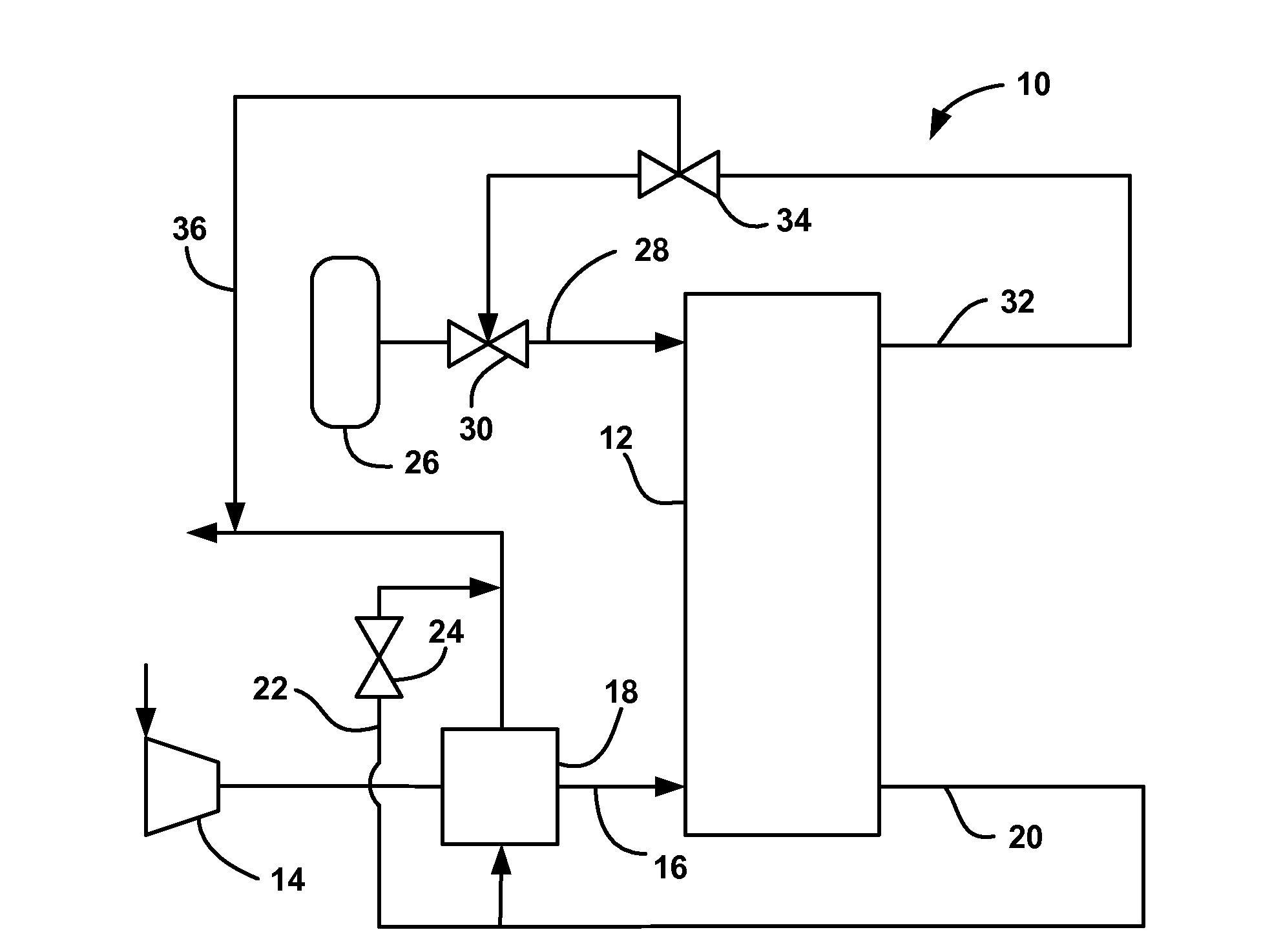
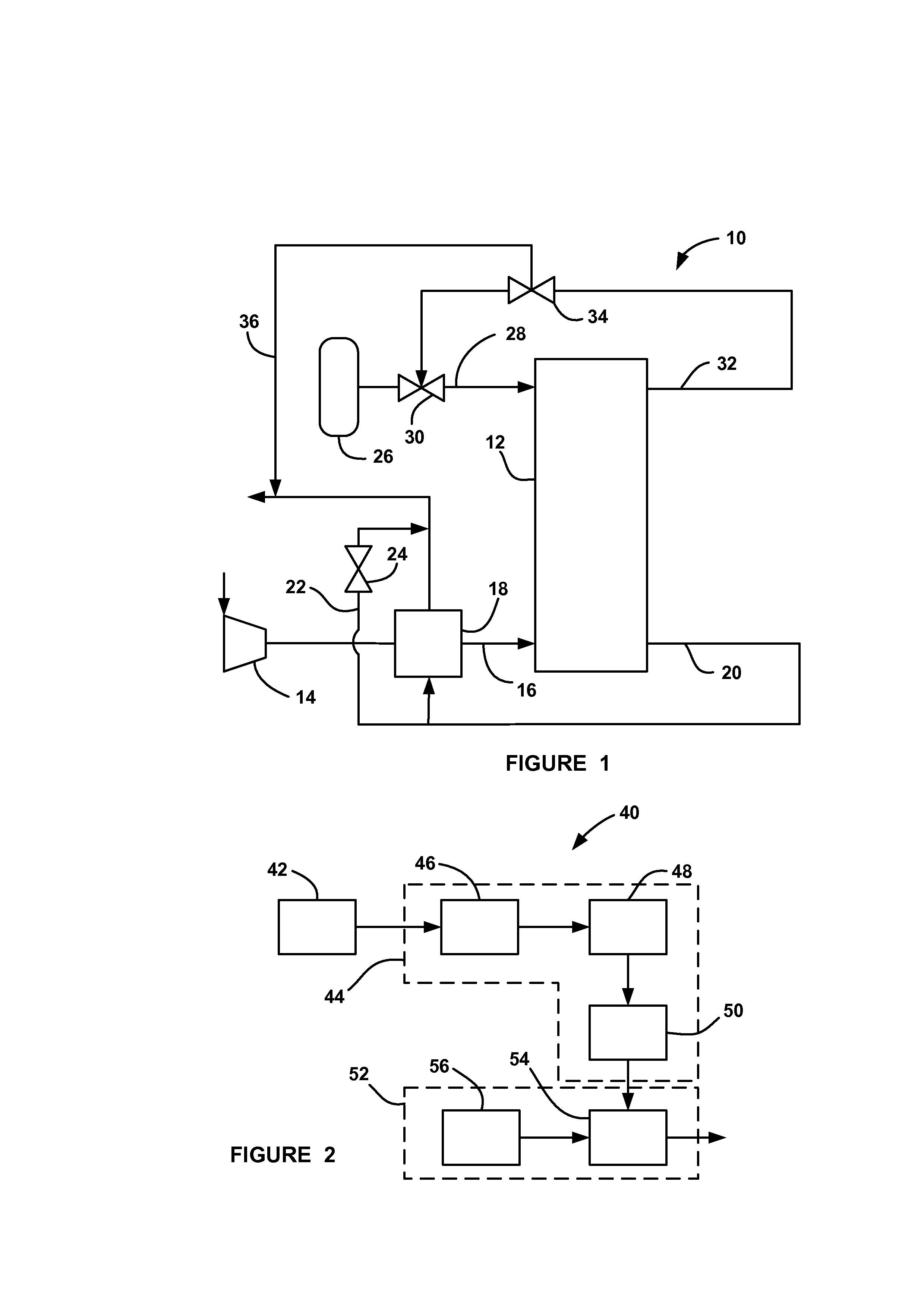
[0022]FIG. 1 is a schematic block diagram of a fuel cell system 10 including a fuel cell stack 12. A compressor 14 provides airflow to the cathode side of the fuel cell stack 12 on a cathode input line 16 through, for example, a water vapor transfer (WVT) unit 18 that humidifies the cathode input air. A cathode exhaust gas is output from the stack 12 on a cathode exhaust gas line 20, which directs the cathode exhaust to the WVT unit 18 to provide...


PUM


Abstract

A system and method for reducing the frequency of stack stand-by mode events, if necessary, as a fuel cell stack ages and experiences lower performance. The method determines an irreversible voltage loss of the fuel cell stack at predetermined time intervals and determines a stack voltage degradation variable based on the irreversible voltage loss. The method also determines if the stack voltage degradation variable indicates that the fuel cell stack will not meet predetermined stack end-of-life voltage requirements and calculates a maximum allowed voltage degradation rate of the fuel cell stack. The method calculates a maximum number of stand-by mode events per unit time that can be allowed to prevent the stack from exceeding the maximum allowed degradation rate and controls the number of stand-by mode events based on the calculated maximum number of stand-by mode events.

Description

BACKGROUND OF THE INVENTION[0001]1. Field of the Invention[0002]This invention relates generally to a system and method for reducing the frequency of fuel cell stack stand-by mode events as the fuel cell stack ages, if necessary, and, more particularly, to a system and method for reducing the frequency of fuel cell stack stand-by mode events as the fuel cell stack ages by determining the irreversible stack voltage loss, and from that assessing if the rate of voltage degradation is too high, where the voltage would be expected to decay below a predetermined limit before the rated end-of-life service of the stack.[0003]2. Discussion of the Related Art[0004]Hydrogen is a very attractive fuel because it is clean and can be used to efficiently produce electricity in a fuel cell. A hydrogen fuel cell is an electro-chemical device that includes an anode and a cathode with an electrolyte therebetween. The anode receives hydrogen gas and the cathode receives oxygen or air. The hydrogen gas i...

Claims


Application Information

Patent Timeline
IPC IPC(8): H01M8/04
CPCH01M8/04955Y02E60/50H01M8/04559
Inventor HARRIS, DANIEL I.LEBZELTER, DEREK R.SALVADOR, JOHN P.PETTIT, WILLIAM H.CHOWDHURY, AKBARHIMES, EDWARD G.
Owner GM GLOBAL TECH OPERATIONS LLC
Why Eureka
Try Eureka