
LED head and photon extractor

a photon extractor and led head technology, applied in the field of semiconductor light sources, can solve the problems of reducing the lifetime of the led head, increasing the absorption, adversely affecting the emission of photons, and forming internal heat, and achieve the effect of improving output capacity and efficiency

Inactive Publication Date: 2013-07-18
BLACKBRITE
View PDF5 Cites 9 Cited by
  • Summary
  • Abstract
  • Description
  • Claims
  • Application Information

AI Technical Summary

Benefits of technology

The present invention provides a semiconductor based light source that has an improved output capacity and efficiency. This is achieved by increasing the critical angle for emission of light from the emitting surface semiconductor chip to the surroundings, which in turn increases the number of photons emitted per time unit. Additionally, the heat transfer through the surface of the semiconductor based light source is increased, which provides improved heat dissipation and cooling of the semiconductor chip, and contributes to increasing the efficiency of the semiconductor based light source. A heat transfer means is also provided that is simple and reliable in achieving improved heat dissipation and cooling of the semiconductor device, and is very cheap in production.

Problems solved by technology

LED lifetime decreases with temperature rise due to poor heat dissipation and recombination of photons to electrons which output phonons that ultimately converge to heat inside the LED chip.
LED chips contacts the encapsulating resin, which in many cases have low thermal conductivity and in particular short wavelength LED's deteriorate the encapsulating resin over time in a way that increase absorption and adversely effect the emission of photons and the formation of internal heat.

Method used


Image

  • LED head and photon extractor
  • LED head and photon extractor
  • LED head and photon extractor

Examples


embodiment 1

[0065] The light source according to the first aspect of the invention, further comprising a heat sink connected to the back part.

embodiment 2

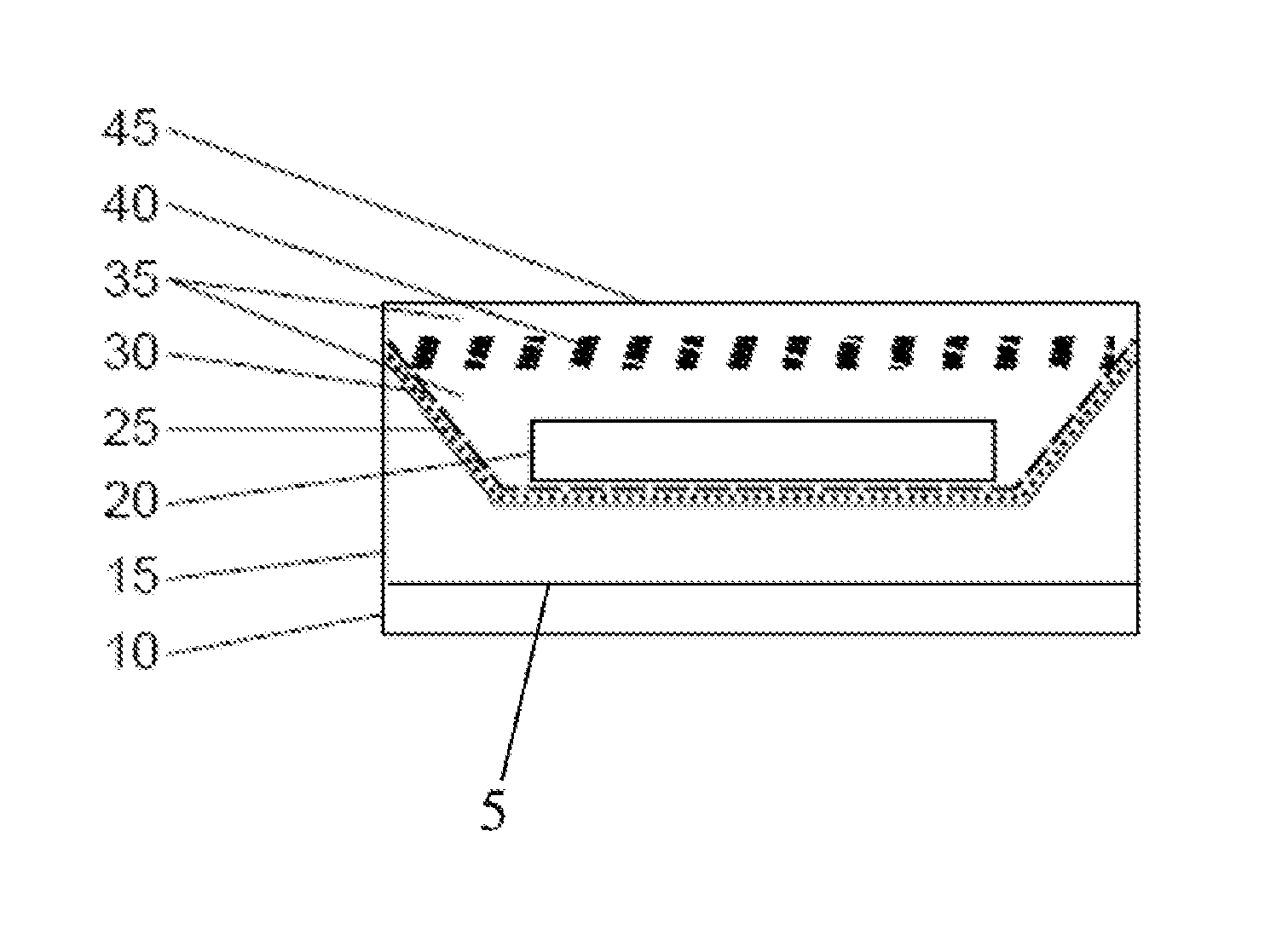
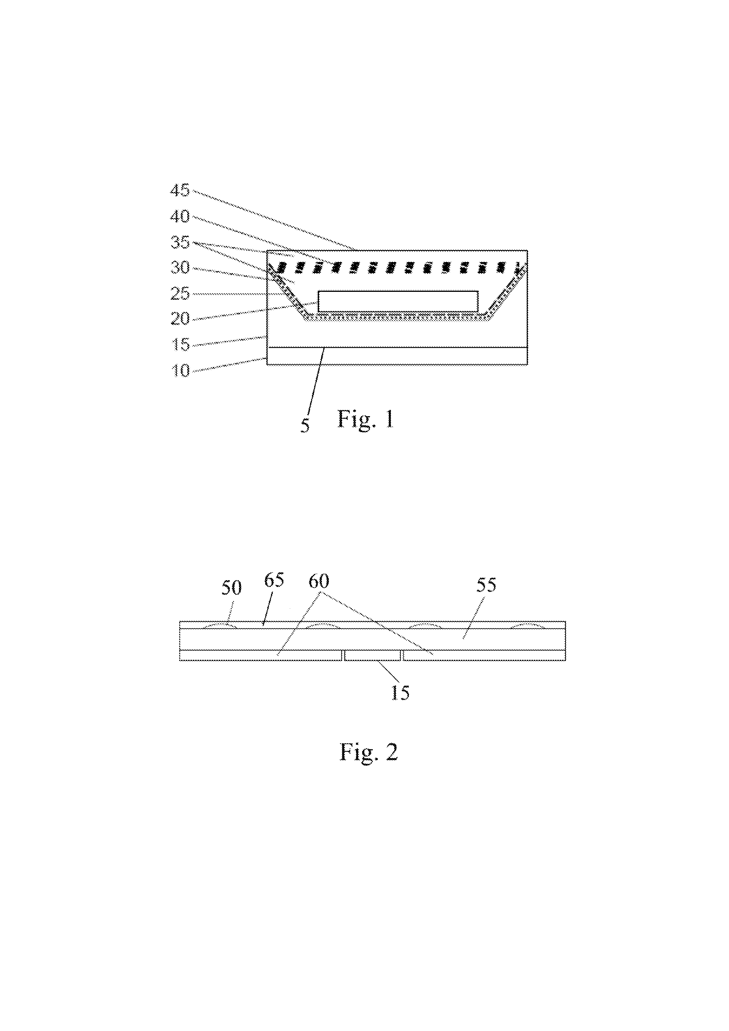
[0066] The light source according to the first aspect of the invention, wherein one or more semiconductor light sources are mounted on a waveguide device built as a laminate comprising a metallic member, an inner low n layer, a high n transparent waveguide, phosphors dots and an outer protective low n layer.

[0067]Embodiment 3. The light source of embodiment 2, wherein said inner low n layer is transparent, colour filtering or opaque, and / or the outer protective low n layer is index matched to the waveguide or to the high n layer.

[0068]Embodiment 4. The light source of embodiment 2, further comprising a metal mirror layer arranged between the metal member and the inner low n layer.

[0069]Embodiment 5. The light source of embodiment 2, further comprising a diffusive low n layer.

[0070]Embodiment 6. The light source of embodiment 2, wherein the phosphor dots comprise a varying fill factor and control coloured text, graphics, illumination areas and intensity of emittance.

embodiment 7

[0071] The light source according to the first aspect of the invention, wherein one or more packaged semiconductor chips are mounted to a waveguide passing through a metallic heat sink adapted to dissipate heat via convection.

[0072]Embodiment 8. The light source of embodiment 7, wherein the metallic heat sink comprising spiraling air channels such as to increase the area of the heat sink in contact with air and through draft pull more air past the surface of the heat sink.

[0073]Embodiment 9. The light source of embodiment 8, wherein at least one of the metal parts of the metallic heat sink is a blow-moulded or a cast aluminum part.


PUM


Abstract

The invention concerns a semiconductor based light source comprising a back part, a front side and at least one semiconductor chip having an emitting surface, at least one reflective optical element being arranged below said at least one semiconductor chip, a material with low refractive index being disposed on a side of said reflective optical element facing said front side, wherein said semiconductor based light source comprises on said front side a compound material with high refractive index having at least one diffractive optical element embedded therein, such as to direct light incident on said diffractive optical element towards preferred directions.

Description

FIELD OF THE INVENTION[0001]The present invention relates in a first aspect to semiconductor light sources, particularly light emitting diodes (LED), and has particular applicability in the field of packaged light emitting diodes (LED). In a second aspect the present invention relates to a heat transfer means for semiconductor devices.BACKGROUND[0002]Generally, an LED consists of a chip of a semiconductor material, such as gallium arsenide (GAAS), gallium nitride (GAN), indium gallium nitride (INGAN) or the like, doped with impurities, such as to create a so-called p-n junction in which a current flows from the p-side, or anode, to the n-side, or cathode, but not in the reverse direction.[0003]Most materials used for LEDs have very high refractive indices. Hence, much light will be TIR and Fresnel reflected back into the material at the material / air surface interface. Thus, light extraction in LEDs is an important aspect of LED production, subject to much research and development.[0...

Claims


Application Information

Patent Timeline
Patent Type & Authority Applications(United States)
IPC IPC(8): F21V13/04F21V7/00
CPCG02B6/0041G02B6/0073H01L33/54H01L33/56H01L33/58H01L33/60H01L33/641H01L2924/0002F21V7/00F21V7/0091F21V13/04H01L2924/00
Inventor OSTERGAARD WAGENBLAST STUBBE, JENSSVENSSON, DAVID
Owner BLACKBRITE
Learn More