Method for Manufacturing Ceramic Member, and Ceramic Member, Gas Sensor Device, Fuel Cell Device, Multi-Layer Piezoelectric Device, Injection Apparatus and Fuel Injection System

a technology of ceramic parts and ceramic components, which is applied in the field of ceramic parts manufacturing, can solve the problems of device consuming more electricity and insufficient sintering of electrodes

Active Publication Date: 2013-07-18
KYOCERA CORP
View PDF4 Cites 0 Cited by
  • Summary
  • Abstract
  • Description
  • Claims
  • Application Information

AI Technical Summary

Benefits of technology

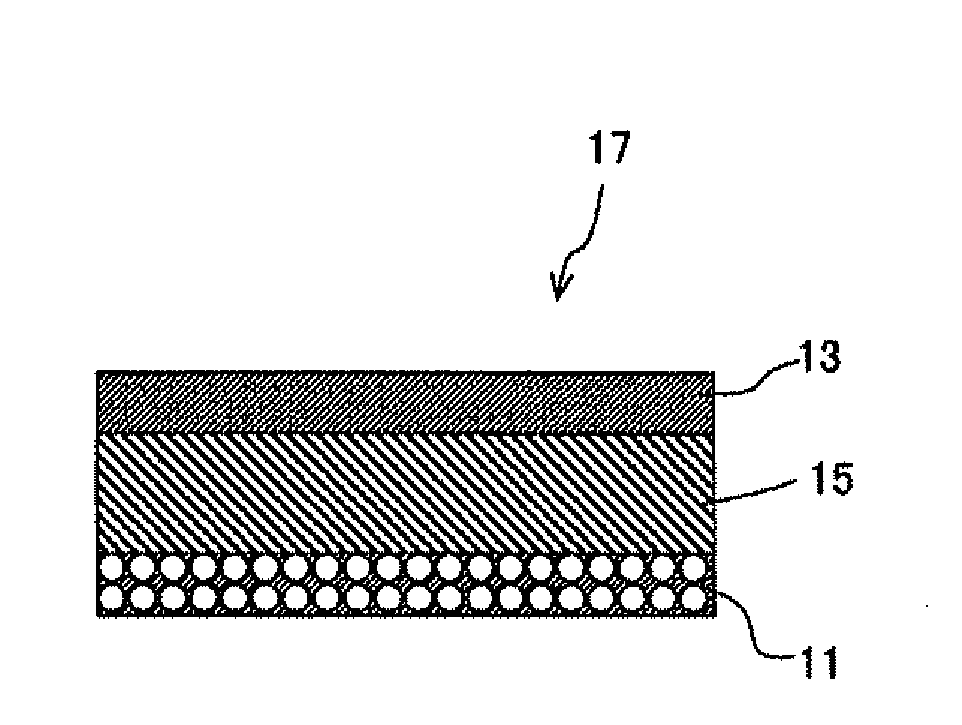
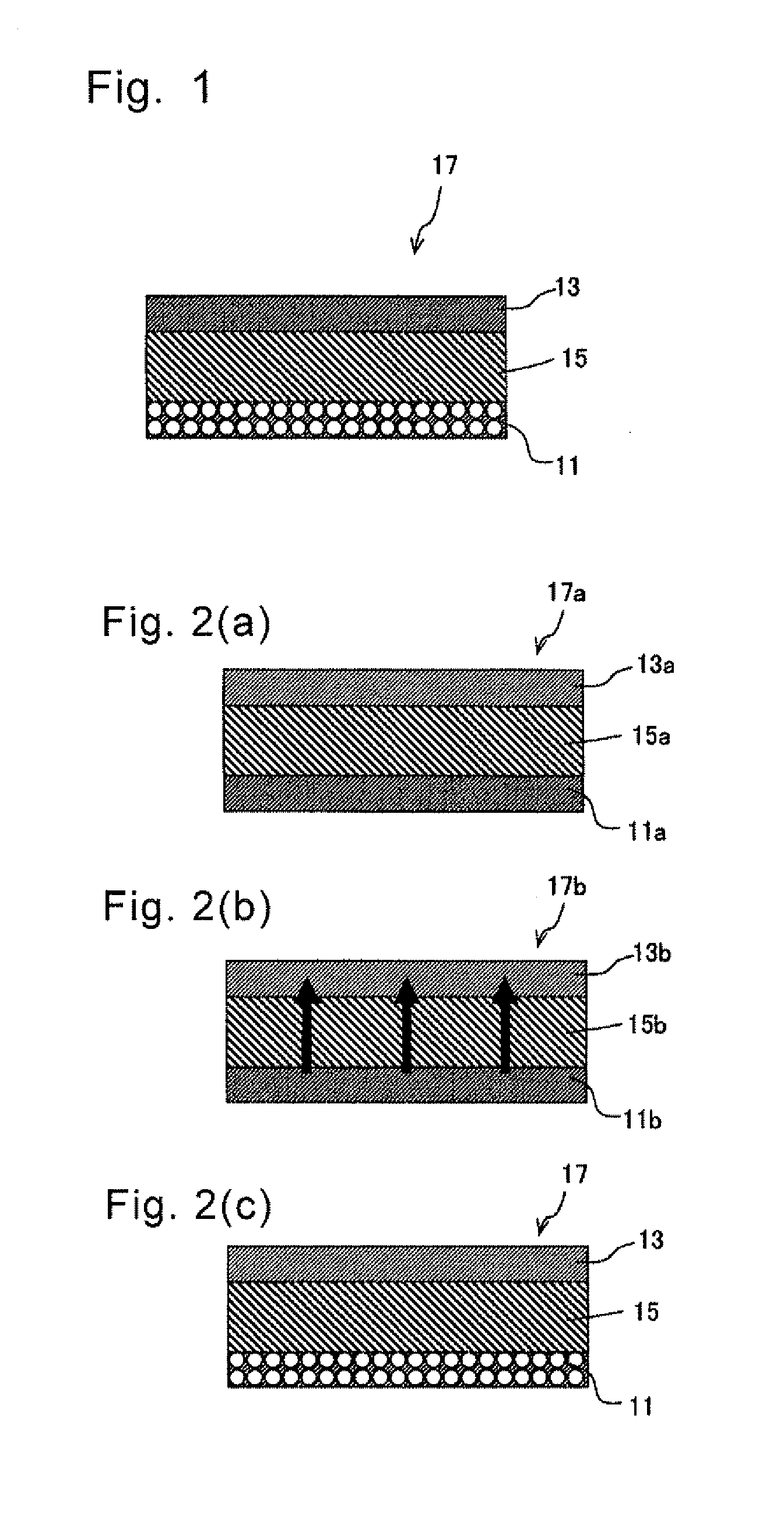
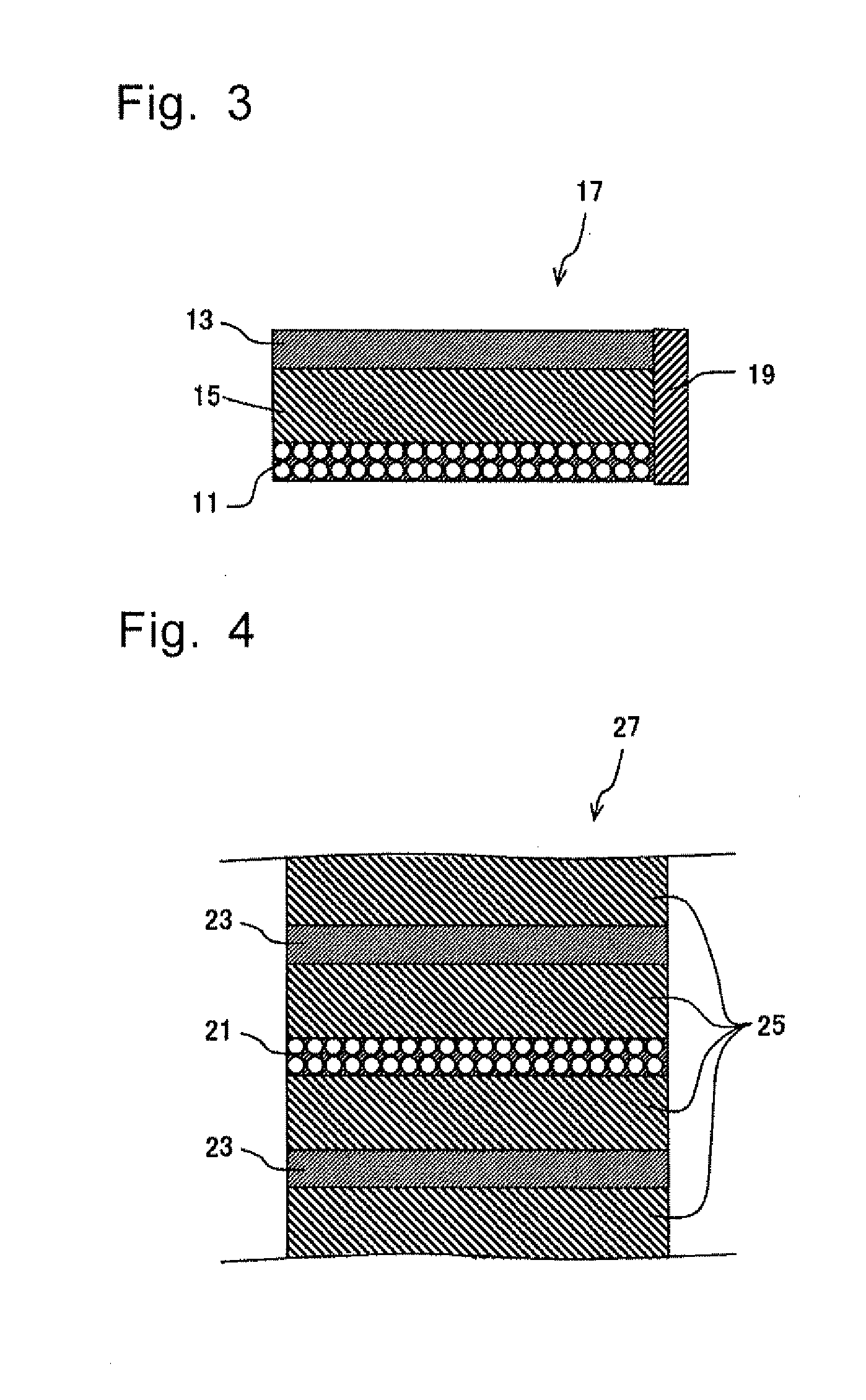
[0007]In a typical method for manufacturing a ceramic member of the present invention, at least one of plural metallic paste layers is formed as the second metallic paste layer that has a higher mass percentage X than that of the first metallic paste layer that adjoins therewith in the stacking direction. As the stacked compact is fired with the mass percentage X of the metal component M1 differentiated (rendered a concentration gradient) between the metallic paste layers that adjoin via the ceramic green sheet, it is made possible to cause the metal component M1 to diffuse through the ceramic layer from a layer having a higher mass percentage X to a layer having lower mass percentage X. Since the metal layer formed by sintering the second metallic paste layer shrinks in volume as the metal component M1 diffuses, a void ratio of the second metal layer increases. Thus the manufacturing method of the present invention makes it possible to manufacture the ceramic member having the metal layers that include many voids by firing the stacked compact having such a constitution as the mass percentage X of the metal component M1 is differentiated between the first metallic paste layer and the second metallic paste layer that adjoin each other via the ceramic green sheet.

Problems solved by technology

With the prior art method of forming the metal layer having a high void ratio, there have been such cases as sintering of the electrode does not proceed sufficiently while the ceramics is sintered sufficiently during simultaneous firing.
This makes it necessary to increase the drive voltage, which causes the device to consume more electricity.

Method used


Image

  • Method for Manufacturing Ceramic Member, and Ceramic Member, Gas Sensor Device, Fuel Cell Device, Multi-Layer Piezoelectric Device, Injection Apparatus and Fuel Injection System
  • Method for Manufacturing Ceramic Member, and Ceramic Member, Gas Sensor Device, Fuel Cell Device, Multi-Layer Piezoelectric Device, Injection Apparatus and Fuel Injection System
  • Method for Manufacturing Ceramic Member, and Ceramic Member, Gas Sensor Device, Fuel Cell Device, Multi-Layer Piezoelectric Device, Injection Apparatus and Fuel Injection System

Examples


example 1

Gas Sensor

[0237]A gas sensor device comprising a ceramic member of the present invention was manufactured as follows. First, a zirconia powder consisting mainly of a stabilized zirconia (5 mol % Y2O3-containing ZrO2) powder having a mean particle size of 0.4 μm, a glass powder, a binder, and a plasticizer were mixed to prepare a slurry. The slurry was formed into a ceramic green sheet having a thickness of 150 μm by a doctor blade method.

[0238]Then, on one surface of the ceramic green sheet, an electrically conductive paste prepared by adding a binder to a raw powder such as a silver alloy powder with the composition shown in Table 1 was printed in a thickness of 30 μm using a screen printing method. At this time, with respect to the portion to be provided with a heating element, a heating element pattern was printed in the shape of a folded zigzag shape. Then, the respective green sheets were stacked to obtain a stacked compact having a shape shown in FIG. 14. Regarding the positio...

example 2

Fuel Cell

[0244]A fuel cell device comprising a ceramic member of the present invention was manufactured as follows. First, a zirconia powder consisting mainly of a cordierite (5 mol % Y2O3-containing ZrO2) powder having a mean particle size of 0.4 μm, a glass powder, a binder, and a plasticizer were mixed to prepare a slurry. The slurry was formed into a ceramic green sheet having a thickness of 150 μm by a doctor blade method.

[0245]On one surface of the ceramic green sheet, an electrically conductive paste prepared by adding a binder to a raw powder such as a silver alloy powder with the composition shown in Table 2 was printed in a thickness of 30 μm using a screen printing method. Then, the respective green sheets were stacked to obtain a stacked compact having a shape shown in FIG. 17. Regarding the position where a predetermined thickness of a ceramic layer is required, a required number of only green sheets were stacked without printing the electrically conductive paste.

[0246]...

example 3

Multi-Layer Piezoelectric Device

[0250]A multi-layer piezoelectric device comprising a ceramic member of the present invention was manufactured as follows. First, a raw powder consisting mainly of a lead titanate zirconate (PZT) powder having a mean particle size of 0.4 μm, a binder, and a plasticizer were mixed to prepare a slurry. The slurry was formed into a ceramic green sheet having a thickness of 150 μm by a doctor blade method. On one surface of the ceramic green sheet, an electrically conductive paste prepared by adding a binder to a raw powder such as a silver alloy powder with the composition shown in Table 3 was printed in a thickness of 30 μm using a screen printing method. To a metallic paste layer for forming a lump containing layer 95, a lead titanate zirconate (PZT) powder having a mean particle size of 0.4 μm was added in the amount of 1% by mass based on the metal powder.

[0251]Then, green sheets were stacked to obtain a stacked compact having a shape shown in FIG. 1...


PUM

PropertyMeasurementUnit
thicknessesaaaaaaaaaa
temperatureaaaaaaaaaa
void ratioaaaaaaaaaa

Abstract

A ceramic member in which the metal layers with high void ratio are sufficiently sintered to lower a residue of resin is produced.The method for manufacturing a ceramic member which comprises a step of forming a stacked compact from a plurality of metallic paste layers containing a metal component M1 that are stacked one on another via ceramic green sheets, and a step of firing the stacked compact, wherein at least one of plural metallic paste layers is formed as a second metallic paste layer that has the mass percentage X higher than that of the metallic paste layer that adjoin therewith in the stacking direction, the mass percentage X being the proportion of the metal component M1 to the total metal content in the metallic paste layer.

Description

TECHNICAL FIELD[0001]The present invention relates to a method for manufacturing a ceramic member, and the ceramic member manufactured thereby. More particularly, the present invention relates to a gas sensor device used in, for example, monitoring indoor atmosphere, atmosphere in a cave or tunnel and exhaust gas, a fuel cell device used in power generation or the like and a multi-layer piezoelectric device to be used in a fuel injection system of automobile engine, a micro movement drive apparatus, a piezoelectric sensor device, a piezoelectric circuit, etc., and methods for manufacturing the same.BACKGROUND ART[0002]The gas sensor device and the fuel cell device have functions to bring a gas into contact with the ceramic members that constitute these devices, so as to have particular component of the gas adsorbed onto the ceramic surface or permeate therethrough. To provide this function, such attempts have been made as forming metal layers (electrodes) in a highly porous structur...

Claims


Application Information

Patent Timeline
Patent Type & Authority Applications(United States)
IPC IPC(8): B22F7/08G01N27/409H01L41/083H01L41/08H01L41/187H01L41/273H01L41/297H02N2/00
CPCG01N27/4073H01L41/0471H01L41/0477H01L41/0838Y10T428/2495H01M8/1246Y02E60/521Y02E60/525B22F7/08H01L41/273Y10T428/249981Y02E60/50Y02P70/50H10N30/871H10N30/877H10N30/508H10N30/053
Inventor OKAMURA, TAKESHIKAWAMOTO, TOMOHIRONAKAMURA, SHIGENOBU
Owner KYOCERA CORP
Why Eureka
Try Eureka