

Composite separator for electrochemical cell and method for its manufacture
a technology of electrochemical cells and separator membranes, applied in the field of electrochemical cells, can solve the problems of high tendency to crack, poor properties of separators, and significant impact on battery performance attributes, and achieve the effects of low cost, convenient use, and efficient production
- Summary
- Abstract
- Description
- Claims
- Application Information
AI Technical Summary
Benefits of technology
Problems solved by technology
Method used
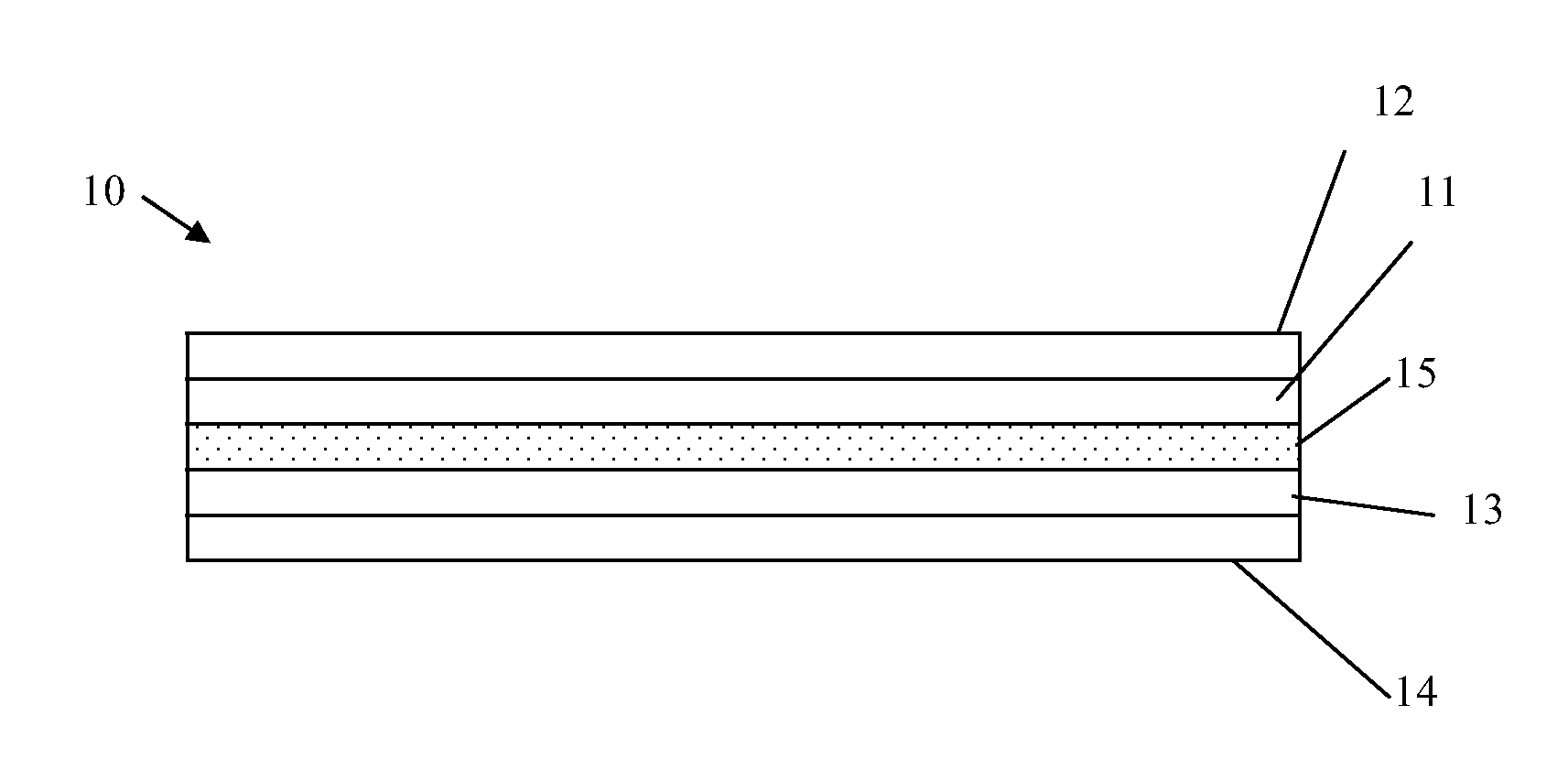
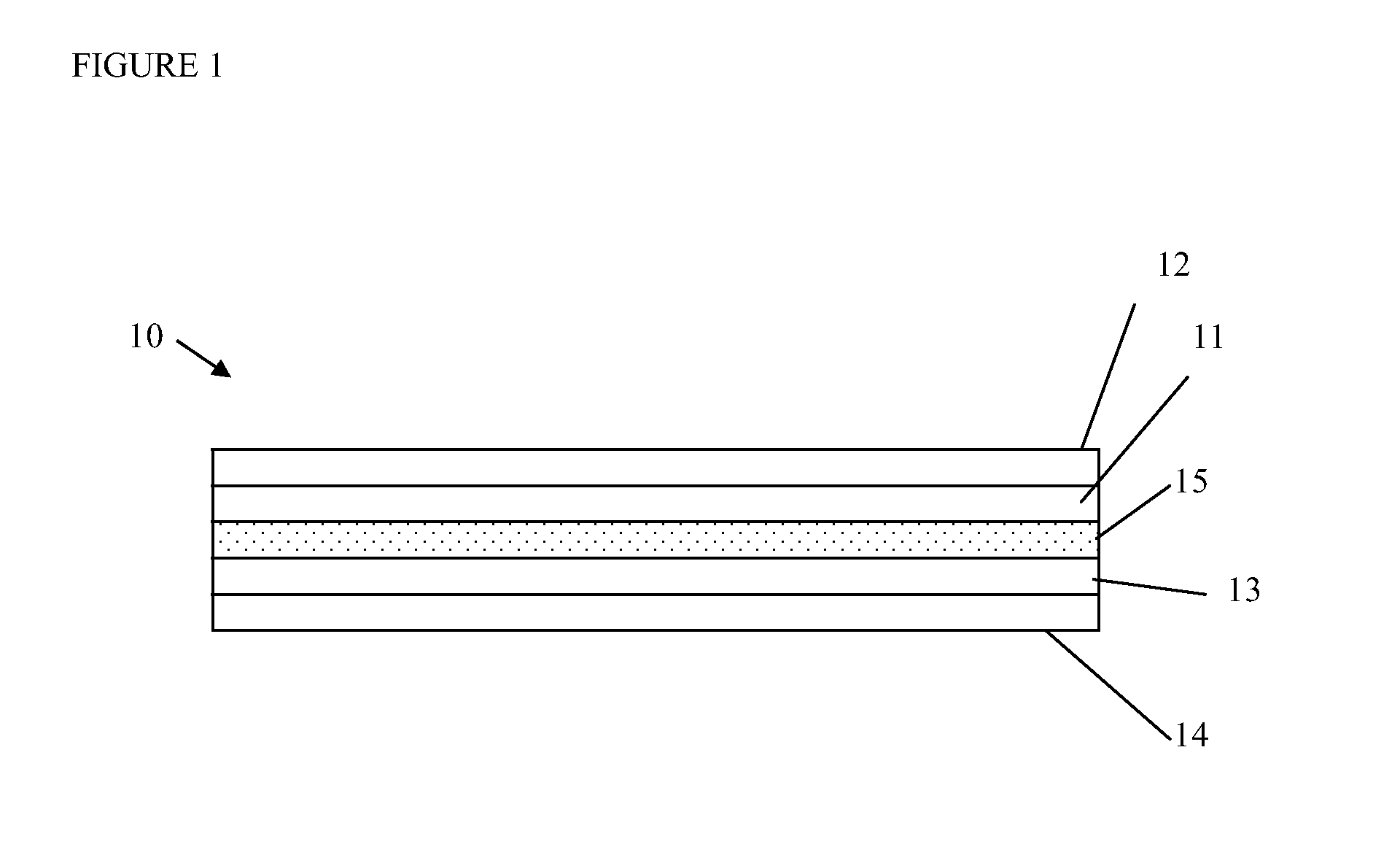
Image

Examples
example 1
Preparation of a Porous Separator
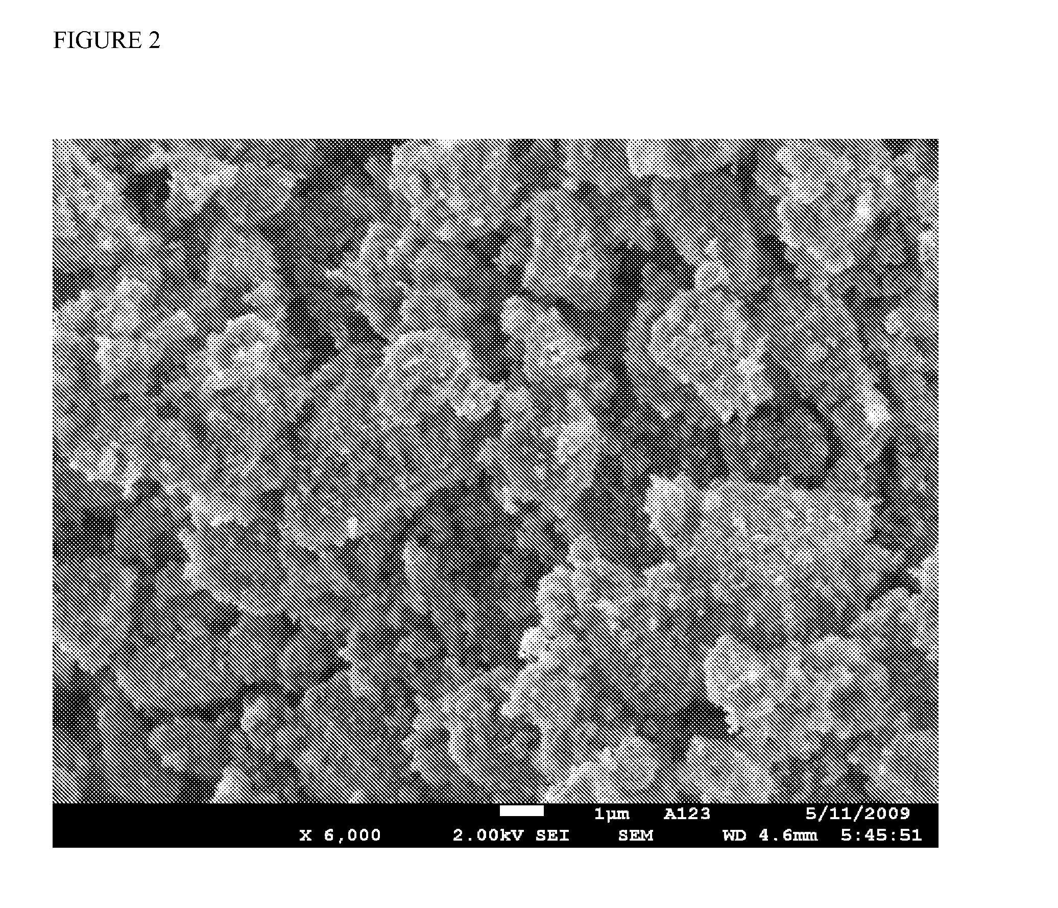
[0099]Membranes for lithium-ion cells were prepared from a mixture of larger particle silica and PVDF. Membranes were prepared from Kureha 7208 PVDF-NMP solution and silica with an average particle size of 3.4-4.0 μm available from W.R. Grace under the trade name Syloid C803. The final coating mixture had a ratio of silica:polymer of 65:35 on a weight basis, and a 12% loading of these solids in a 40:60 (volume / volume) mixture of NMP and cyclohexanone blend.
[0100]A polymer pre-paste was formed initially as a high solids content viscous mixture. The resultant mixture was then blended with additional NMP and cyclohexanone to obtain the desired solids content and solvent blend. Mixer is a Speed Mixer DAC 600 FVZ from Flack Tek Inc.
[0101]To prepare the polymer pre-paste, the silica was added to a portion of the total polymer binder (40% of ultimate total binder solution volume) in three increments (typically 40%, 40%, and 20%). After each incremental addi...
example 2
Comparison of Coated Separators in Pouch Cells
[0106]A porous membrane prepared substantially as described in Example 1 was prepared with the following modifications. The silica separator was laid down either as one layer on a single electrode or as two layers on both the positive and negative electrode, in which each electrode had a layer of one-half the total thickness. In combination, the two separator layers had the same thickness as the single layer. The layers were coated using a slot die coater.
[0107]Cells were prepared as a single layer pouch format by placing the coated cathode made of a lithium iron phosphate material (LFP) directly adjacent to a counter electrode, which is carbon that may or may not also be coated with the composite separator, in a pouch container that is sealed on three sides, filling the cell with electrolyte and then sealing the fourth side so that the interior is totally isolated from the external environment.
[0108]An electrochemical impedance spectros...
PUM
 Abstract
Description
Claims
Application Information