Chamfering of laminate layers

a technology of laminate layers and chamfering, which is applied in the direction of maintenance and safety accessories, grinding machines, liquid fuel engines, etc., can solve the problems of increasing tsub>g /sub> with time, hardening and brittleness of resin, and increasing cold tsub>g /sub>, so as to improve the effect of machine convenience and decreasing temperatur

Active Publication Date: 2013-07-25
VESTAS WIND SYST AS
View PDF3 Cites 16 Cited by
  • Summary
  • Abstract
  • Description
  • Claims
  • Application Information

AI Technical Summary

Benefits of technology

[0011]The resin becomes hard and brittle when cooled, which makes it easier to machine. Generally, the resin becomes harder and more brittle with decreasing temperature. Therefore, it is preferable to cool the material to the lowest temperature possible within realistic practical and economic constraints.

Problems solved by technology

The resin becomes hard and brittle when cooled, which makes it easier to machine.
Generally, the resin becomes harder and more brittle with decreasing temperature.
However, as a matrix ages, some additional cross linking will occur, causing the cold Tg to increase slightly with time.

Method used


Image

  • Chamfering of laminate layers
  • Chamfering of laminate layers
  • Chamfering of laminate layers

Examples


Embodiment Construction

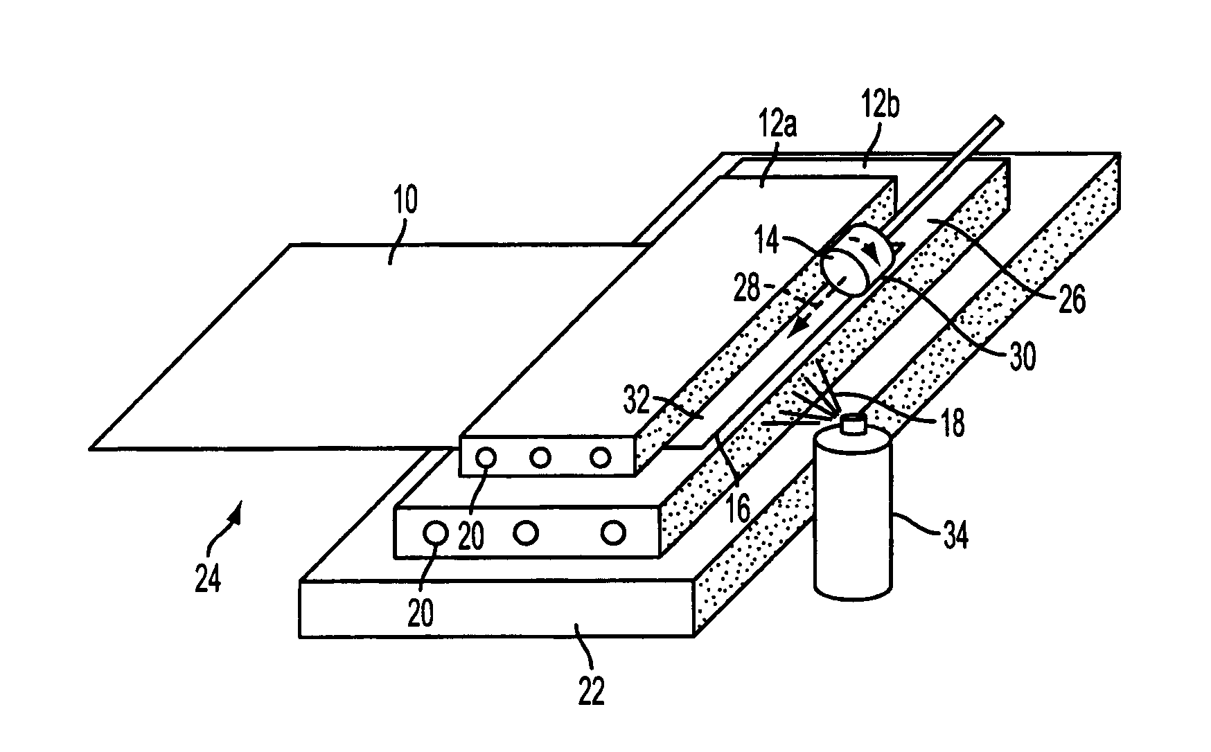
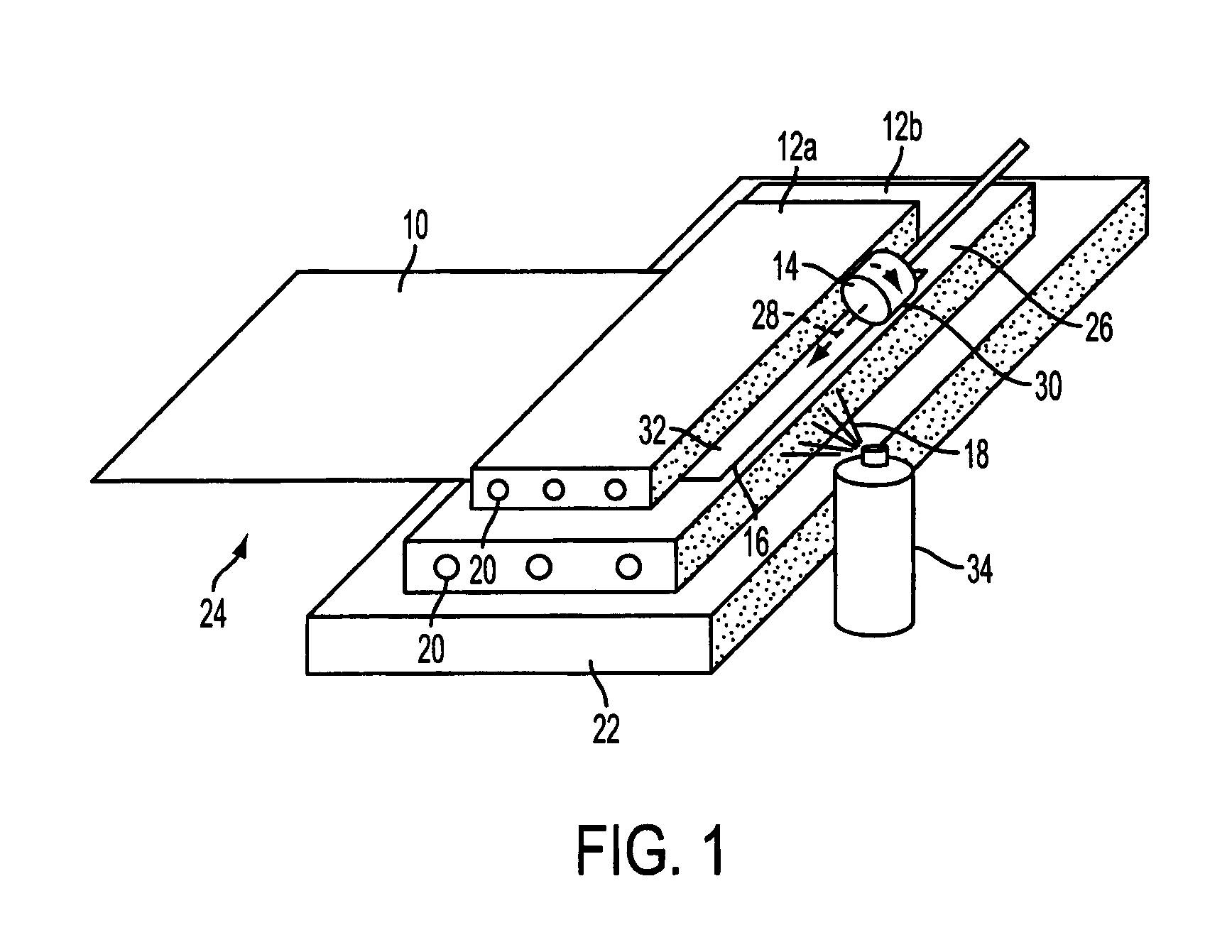
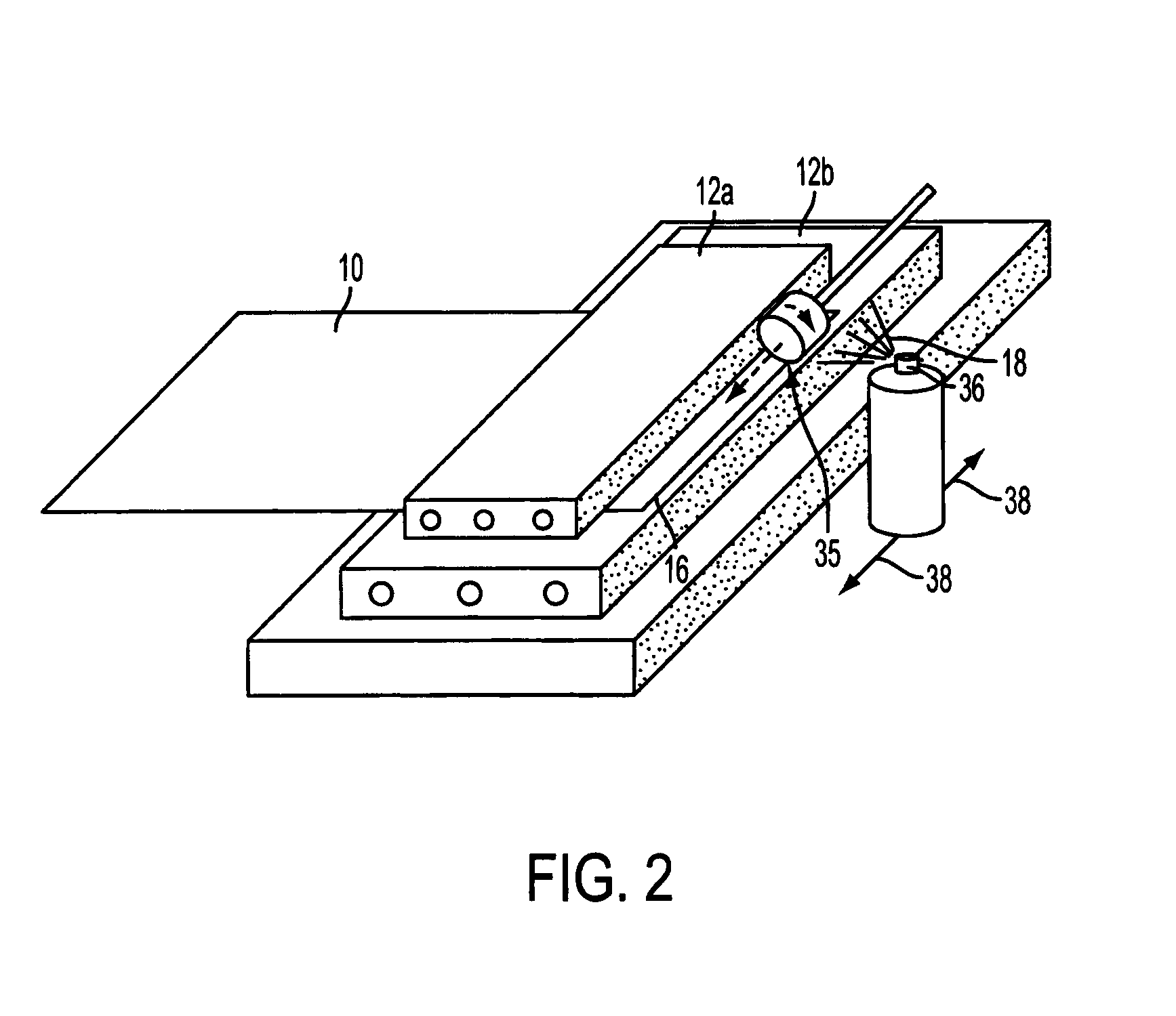
[0022]Referring to FIG. 1, a prepreg ply 10 is clamped between refrigerated steel blocks 12a, 12b, and a grinding wheel 14 is arranged to translate across a free edge 16 of the ply 10 to remove material from that edge to create a chamfer. Refrigerant 18 is applied locally to the free edge 16 of the ply 10 during the chamfering operation. The apparatus and chamfering technique are described in further detail below.

[0023]The prepreg ply 10 comprises a sheet of glass fibre fabric, which has been impregnated with a thermoset matrix, which in this example is pre-catalysed epoxy resin. The glass fibre fabric consists of two layers and is commonly referred to as ‘triax’. The first layer includes a set of unidirectional (ud) fibres, whilst the second layer is a layer of ‘biax’, which has a first set of unidirectional fibres oriented at an angle of +45° relative to the fibres in the first layer, and a second set of unidirectional fibres oriented at an angle of −45° relative to the fibres in ...


PUM

PropertyMeasurementUnit
temperatureaaaaaaaaaa
Tgaaaaaaaaaa

Abstract

A method of machining a fibrous sheet for a composite structure is described. The sheet comprises a resin matrix having a glass transition temperature, wherein the method comprises cooling the sheet substantially to maintain the temperature of the matrix below its glass transition temperature during machining.

Description

[0001]This invention relates to techniques for chamfering layers or plies used in composite structures, such as wind turbine blades.[0002]Composite structures typically comprise one or more plies, each ply being a fibre-reinforced sheet that may comprise a thermoplastic or thermosetting resin matrix. The fibres may be pre-impregnated with the matrix as a ‘prepreg’ or the matrix may be impregnated into a fibre sheet during fabrication of a composite structure, for example during lay-up or injection-moulding procedures. Alternatively, the fibre-reinforced sheet may be pre-impregnated on just one side by a resin foil, i.e. a ‘semi-preg’.[0003]Plies are commonly laid atop one another in a layered or laminated arrangement. Single-ply composite structures are also possible, with single-thickness plies abutting in edge-to-edge relationship or overlapping at their edges. The plies are commonly supported by a foam core to define a skin on or around the core.[0004]In some circumstances, it is...

Claims


Application Information

Patent Timeline
Patent Type & Authority Applications(United States)
IPC IPC(8): B23Q11/10F04D29/38B29C70/54
CPCB24B9/20B24B41/068B24B55/02B29C70/545Y10T29/49995B23Q11/10B29C70/54F04D29/38Y10T29/54B29C2035/165B23Q11/1053B29C2793/0027B29C70/302B24D5/02B29C35/16B29C67/0044
Inventor BELLANGER, YOHANNTHOMSON, CHRISTOPHER
Owner VESTAS WIND SYST AS
Why Eureka
Try Eureka