

Drive apparatus for hybrid vehicle
- Summary
- Abstract
- Description
- Claims
- Application Information
AI Technical Summary
Benefits of technology
Problems solved by technology
Method used
Image

Examples
Embodiment Construction
[0036]Hereinafter, a drive apparatus of a hybrid vehicle according to an exemplary embodiment of the present invention will be described in detail with reference to the drawings. The same or similar element will be denoted by the same reference numeral as that of the drive apparatus of the hybrid vehicle shown in FIG. 6.
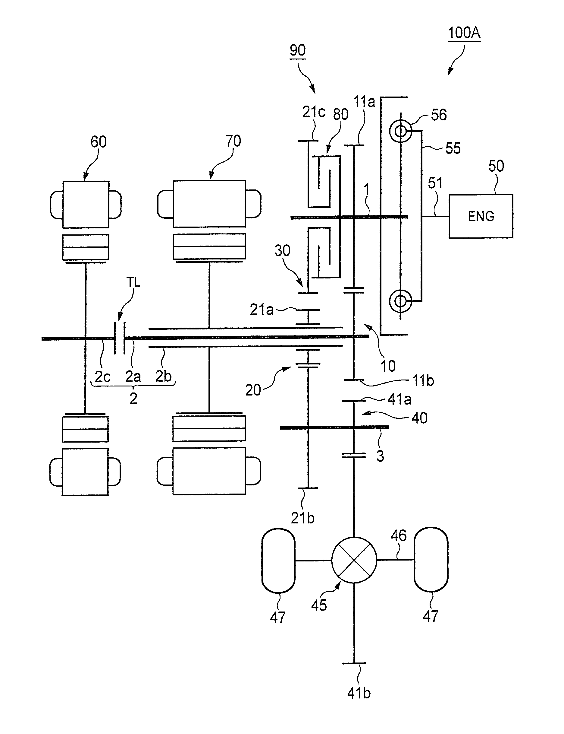
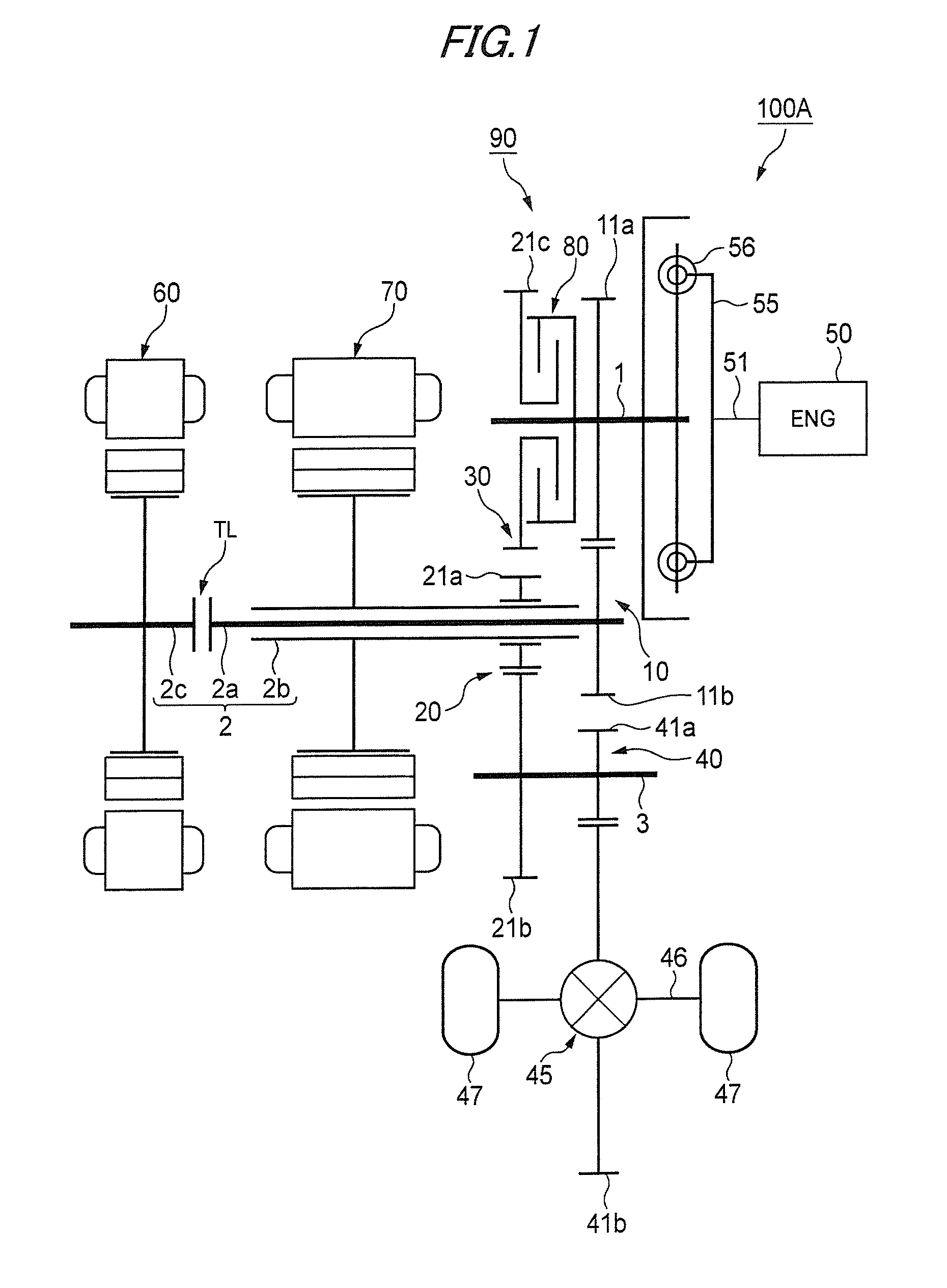
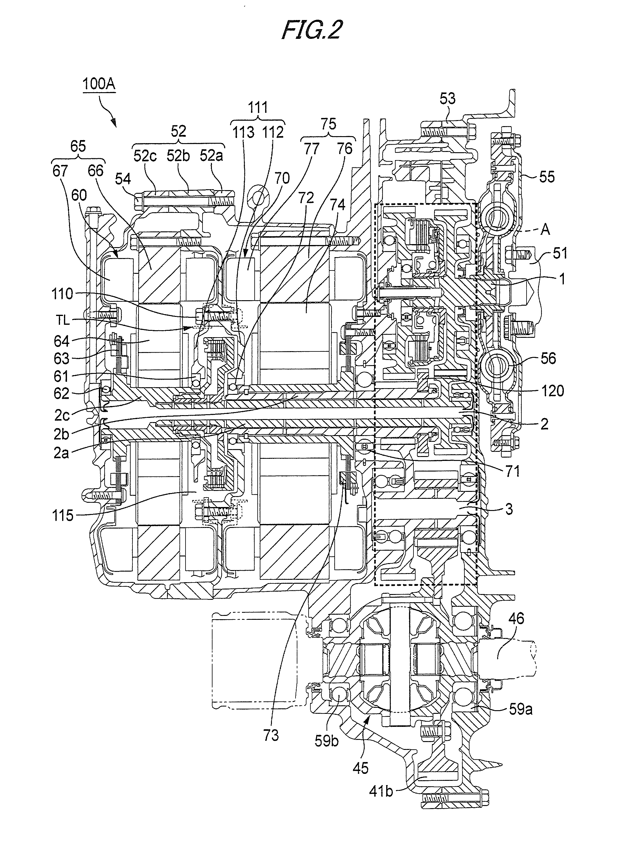
[0037]FIG. 1 is a skeleton diagram of a drive apparatus of a hybrid vehicle according to the present invention, FIG. 2 is a sectional view of the drive apparatus of the hybrid vehicle according to the present invention, FIG. 3 is an enlarged view of a portion indicated by “A” in FIG. 2, and FIG. 4 is an enlarged view of a torque limiter in FIG. 2.
[0038]As shown in FIG. 1, a drive apparatus 100A for a hybrid vehicle of the present embodiment includes an engine 50, a generator 60, a motor 70, and a transmission 90. The transmission 90 includes an engine shaft 1, a motor-generator shaft 2 and an output shaft 3, which are arranged in parallel to each other. Further, the ...
PUM
 Abstract
Description
Claims
Application Information