Arteriovenous Shunt Having a Moveable Valve

a technology of arteriovenous shunt and moveable valve, which is applied in the direction of suction devices, intravenous devices, etc., can solve the problems of lung over-inflation, shortness of breath, and inability to maintain healthy lung tissue to provide the required amount of blood oxygenation

Active Publication Date: 2013-08-08
MEDTRONIC VASCULAR INC
View PDF3 Cites 25 Cited by
  • Summary
  • Abstract
  • Description
  • Claims
  • Application Information

AI Technical Summary

Benefits of technology

[0010]Embodiments hereof also relate to a method for forming a connection between first and second body vessels. A shunt assembly is intravascularly delivered in a collapsed configuration to a tissue track formed from the first vessel to the second vessel. The shunt assembly includes a shunt having a tubular body and a valve extending through and beyond the ends of the shunt. The shunt assembly is radially expanded in the tissue track such that one end of the valve is in a first vessel, and the other end of the valve is in a second vessel. A

Problems solved by technology

As the alveoli and bronchial tubes are destroyed, the remaining healthy lung tissue must work harder to provide the required amount of blood oxygenation.
The need for more air leads to lung over-inflation.
As the lung over-expands, it gradually enlarges, completely filling the chest cavity and causing a sense of shortness of breath.
The lung eventually loses its elasticity an

Method used


Image

  • Arteriovenous Shunt Having a Moveable Valve
  • Arteriovenous Shunt Having a Moveable Valve
  • Arteriovenous Shunt Having a Moveable Valve

Examples


Embodiment Construction

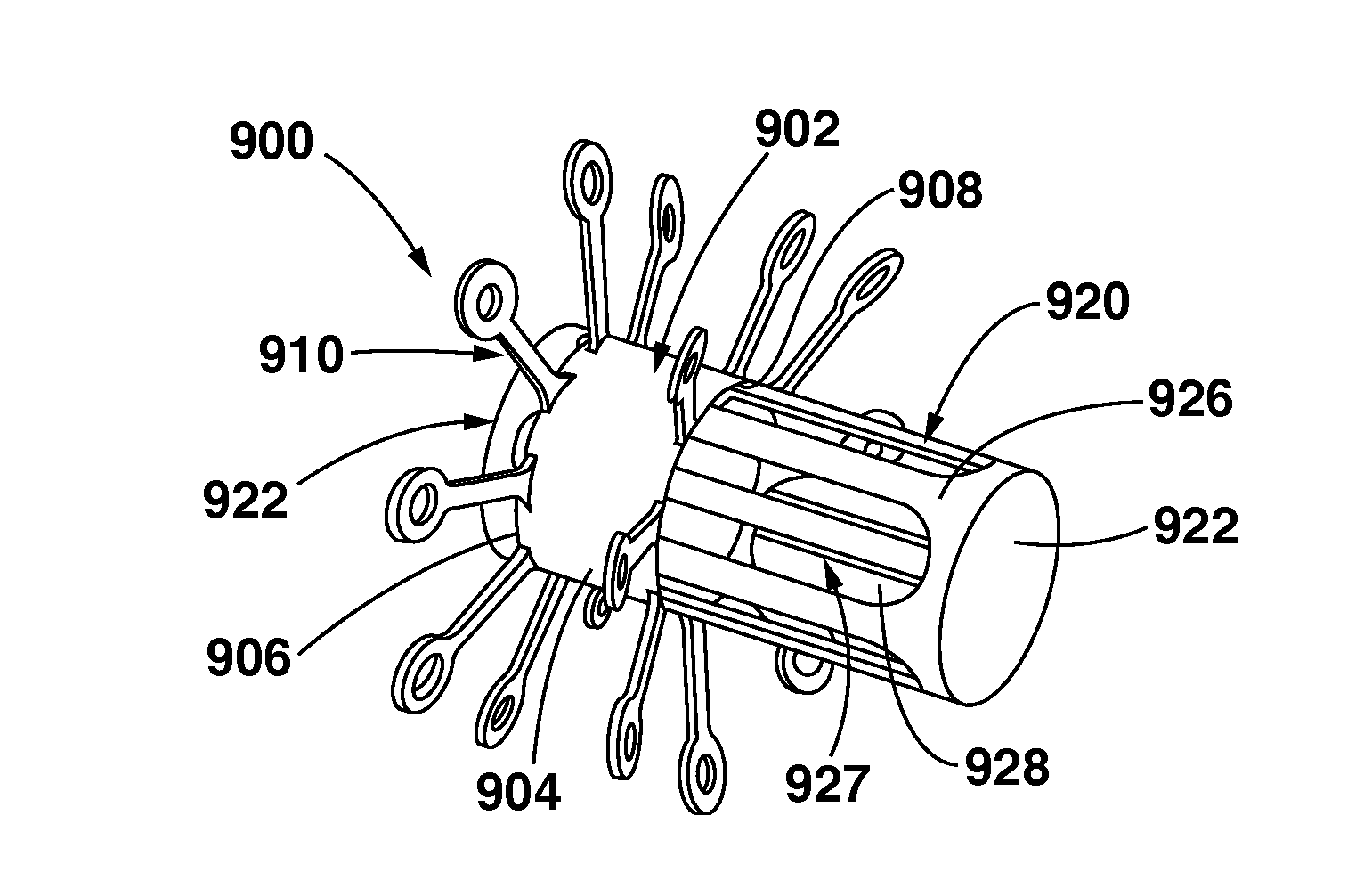
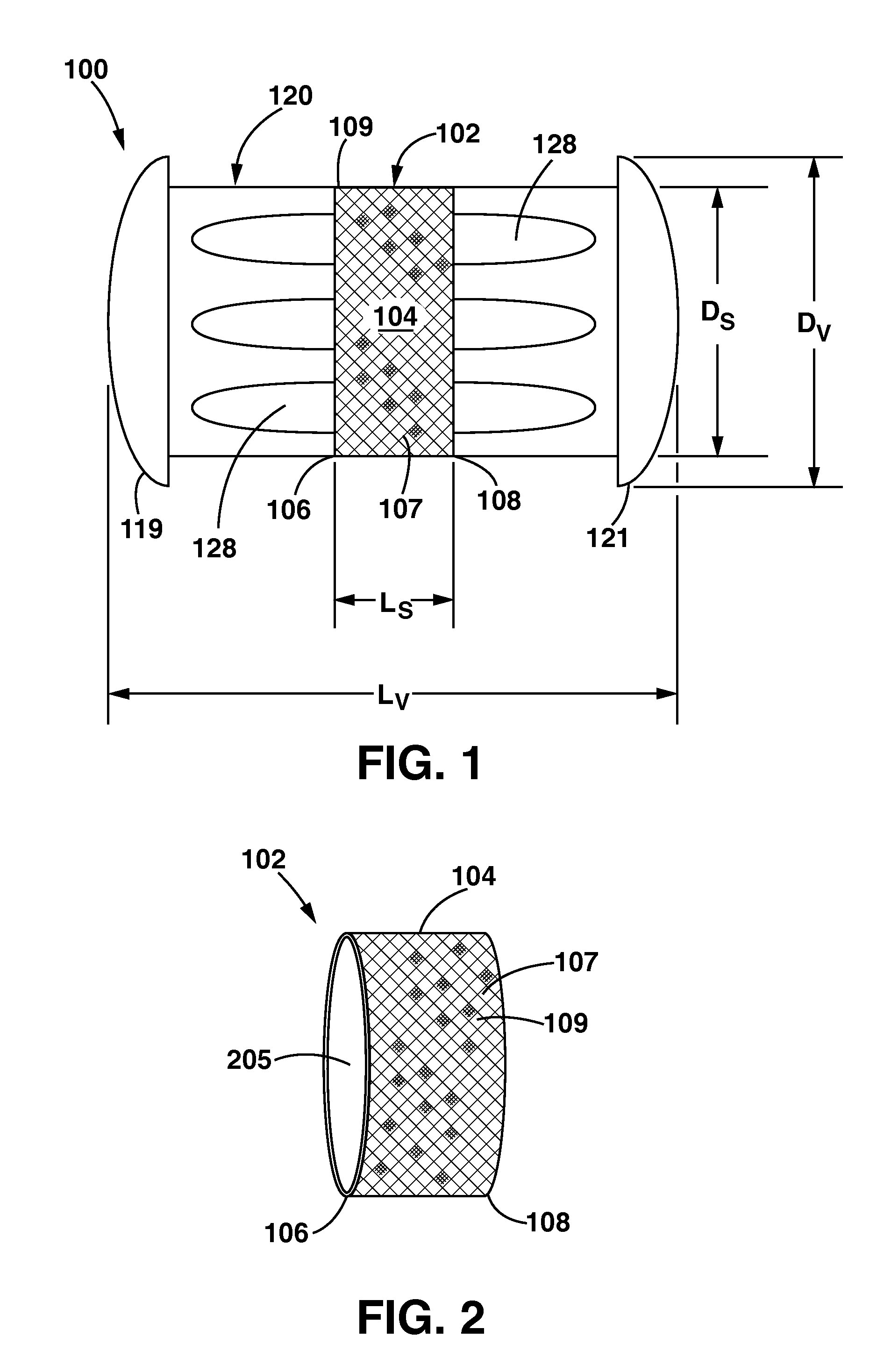
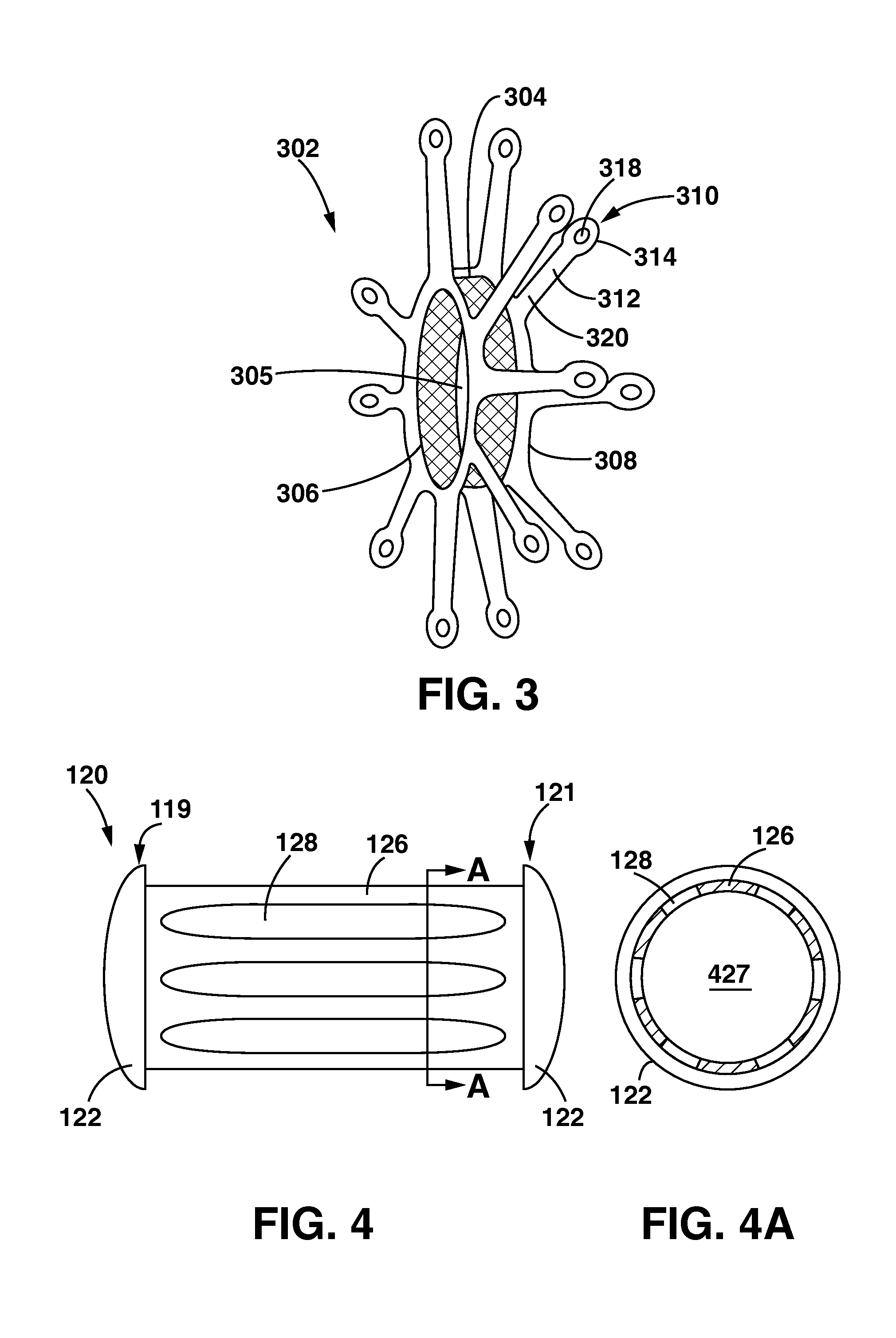
[0028]Specific embodiments of the present invention are now described with reference to the figures, wherein like reference numbers indicate identical or functionally similar elements. The terms “distal” and “proximal” are used in the following description with respect to a position or direction relative to the treating clinician. “Distal” or “distally” are a position distant from or in a direction away from the clinician. “Proximal” and “proximally” are a position near or in a direction toward the clinician. In addition, the term “self-expanding” is used in the following description with respect to components comprising a material that has a mechanical memory to return the component to an expanded deployed configuration from a compressed or constricted delivery configuration. Non-exhaustive examples of such shape memory materials include spring temper stainless steel, a pseudo-elastic metal such as a nickel titanium alloy (nitinol), an elastic polymer, or a so-called super alloy, w...


PUM


Abstract

An arteriovenous shunt assembly including a shunt having a hollow bore between open first and second ends thereof and a valve slidably disposed through the hollow bore. The valve includes means for retaining the valve in a closed position or in any of various selected open positions that provide corresponding different rates of blood flow through the shunt assembly. In some embodiments, the AV shunt assembly is self-expandable from a collapsed tow-profile configuration employed during transluminal delivery. The valve position in the hollow bore may be adjusted in vivo by inflating a catheter balloon in a blood vessel to bear against an end of the valve. Methods for using the shunt assembly are also disclosed.

Description

FIELD OF THE INVENTION[0001]The invention relates to an implantable arteriovenous (AV) shunt assembly having a shunt and a movable valve disposed therein for adjusting the rate of blood flow through the assembly.BACKGROUND OF THE INVENTION[0002]In modern medicine there are numerous treatments in which it is desirable to create shunts or flow-through connections between blood vessels and / or other anatomical structures of the body. Such treatments include, for example, hemodialysis, hemofiltration, hemodiafiltration, plasmapheresis, and extracorporeal membrane oxygenation (ECMO). In many cases, open surgical techniques have been used to form anatomic connections or fistulas between adjacent vessels of body structures. More recently, percutaneous catheter-based techniques and devices have been developed for creating channels or passageways, e.g., shunts between adjacent vessels or anatomical structures.[0003]In addition to the above-listed treatments, arteriovenous (AV) shunt devices h...

Claims


Application Information

Patent Timeline
IPC IPC(8): A61M1/00
CPCA61M1/3655
Inventor DUFFY, NIALLO'SULLIVAN, KEVIN
Owner MEDTRONIC VASCULAR INC
Why Eureka
Try Eureka