
System and Method for Calculating Power Using Contactless Voltage Waveform Shape Sensor

a technology of contactless voltage waveform and shape sensor, which is applied in the field of system and method for measuring ac power with a contactless voltage waveform shape sensor, can solve the problems of grossly inaccurate, prohibitive in terms of both equipment and installation costs, etc., and achieve accurate calculation of actual power consumption, convenient monitoring, and accurate assessment

Active Publication Date: 2013-08-15
NANTENERGY INC
View PDF2 Cites 44 Cited by
  • Summary
  • Abstract
  • Description
  • Claims
  • Application Information

AI Technical Summary

Benefits of technology

The patent describes a system and method that allows for cheap instrumentation of buildings and homes to monitor electrical consumption. This system can also track specific circuits within a building. The installation process does not require any connections or an electrician. The patent also addresses the issue of accurately measuring current, voltage, and phase difference to determine power factor (PF) and calculate actual power consumption.

Problems solved by technology

An important issue in power metering is the need to measure current, voltage, and the phase difference between the two, thereby allowing power factor (PF) to accurately be assessed for each unit.
Conventionally, accurate power measurement requires the installation of individual third party meters on each metered circuit, which is prohibitive in terms of both equipment and installation costs.
These non-contact meters often require synchronization and yield grossly inaccurate results.

Method used


Image

  • System and Method for Calculating Power Using Contactless Voltage Waveform Shape Sensor
  • System and Method for Calculating Power Using Contactless Voltage Waveform Shape Sensor
  • System and Method for Calculating Power Using Contactless Voltage Waveform Shape Sensor

Examples


Embodiment Construction

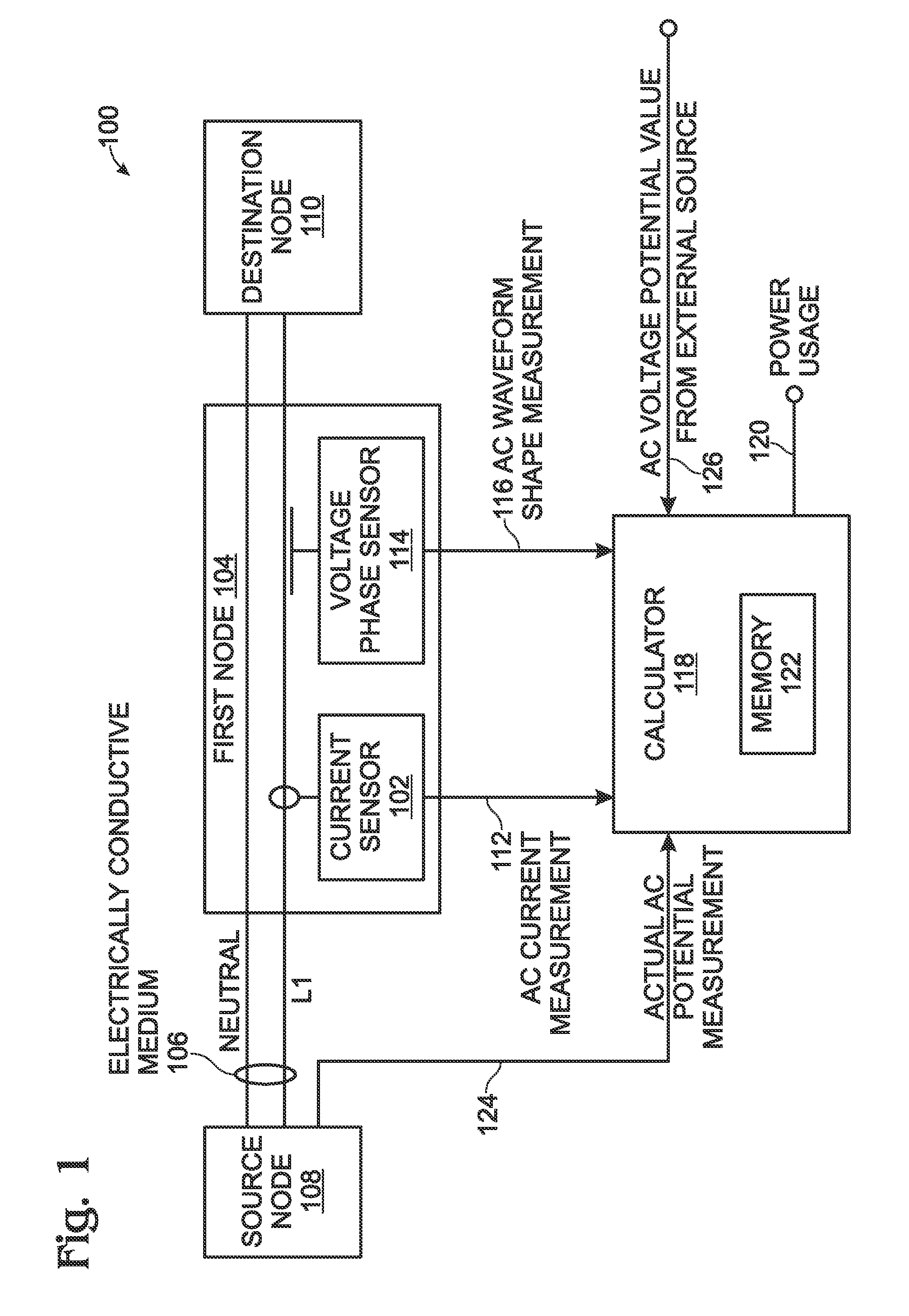
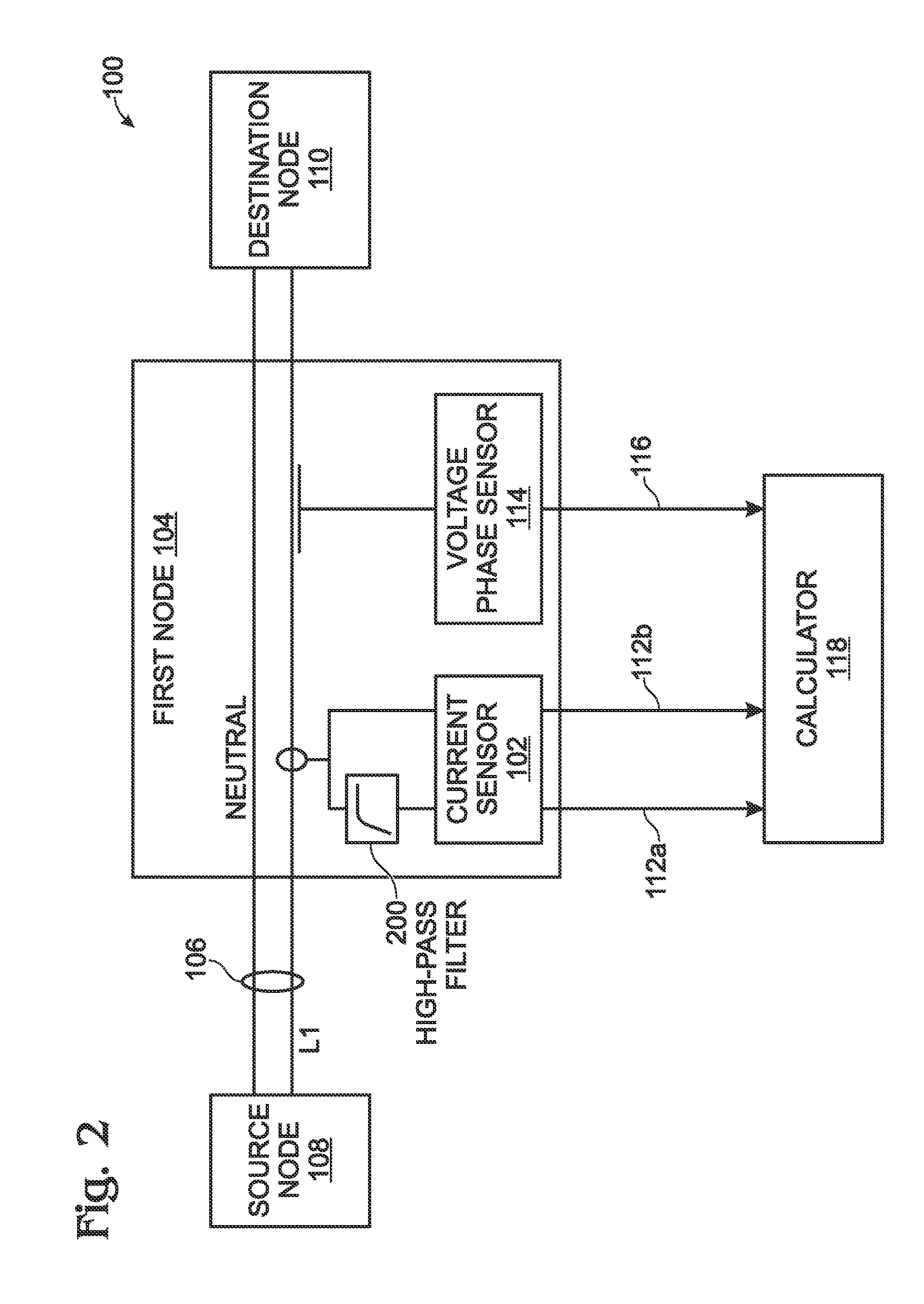
[0037]FIG. 1 is a schematic block diagram of a system for calculating power using a contactless voltage phase sensor. The system 100 comprises a contactless alternating current (AC) current sensor 102 configured to couple to a first node 104 of an electrically conductive medium 106 carrying AC current, associated with an AC voltage. The first node 104 may be located at any point between the source node 108 and the destination node 110. The system 100 may be enabled using any conventional current sensor. For example, a sensor made with a ferrite core transformer measures inductance generated by current, and once calibrated, can yield a current measurement. Alternatively, the AC current sensor may be of the type that actually contacts the conductor. For example, a current meter connected in series may be used, but then the full current runs through the meter. It is more typical to put a shunt resistor in series and then measure the voltage drop across the shunt resister. This makes th...


PUM


Abstract

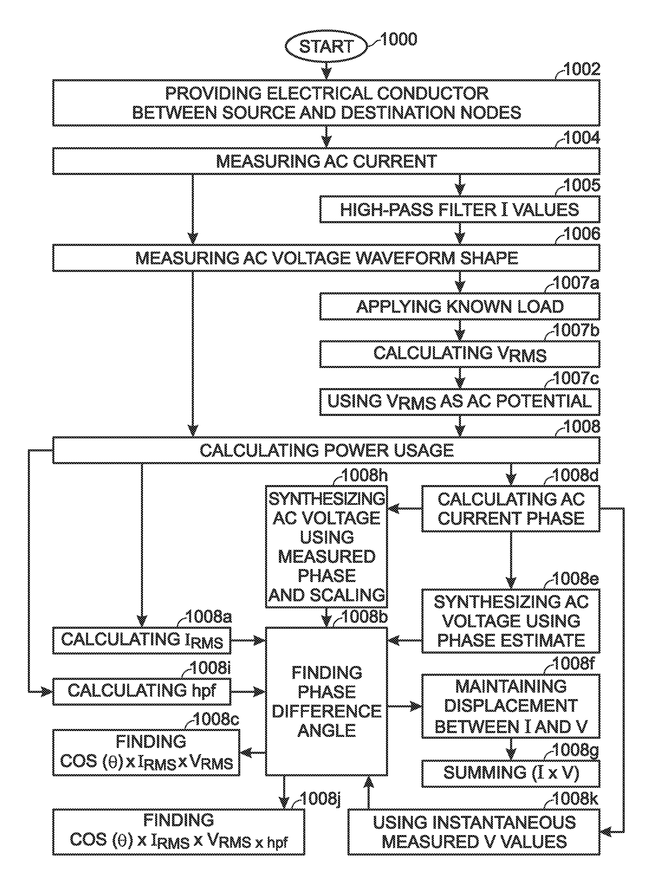
A system and method are provided for calculating power using a voltage waveform shape measurement from a contactless sensor. An electrically conductive medium carries alternating current (AC) electrical current, associated with an AC voltage, from a source node to a destination node. AC current is measured through the electrically conductive medium. Using a contactless sensor, an AC voltage waveform shape is measured. The power usage at the destination node is calculated in response to the AC current measurement, the measurement of the AC voltage waveform shape, and an AC voltage potential. For simplicity, the AC current and AC voltage waveform shape may both be measured at a first node located between the source node and the destination node. The AC voltage potential used in the power usage calculation may be an estimate, an actual measurement, or a value supplied by an external source (e.g., the power utility).

Description

BACKGROUND OF THE INVENTION[0001]1. Field of the Invention[0002]This invention generally relates to alternating current (AC) power measurement and, more particularly, to a system and method for measuring AC power with a contactless voltage waveform shape sensor.[0003]2. Description of the Related Art[0004]The electric energy used in a residence is commonly measured with electric meters that have full access to the electric power conductors feeding that residence. However, the electric meter is typically the property of the local electric utility and the measurements made are generally not available to the residence by automated means. In order for the resident to obtain electric consumption data in near real-time, an additional electric meter is often installed behind the utility's electric meter (at the resident's side). The installation of an additional electric meter generally requires access to the same electric conductors as the utility owned meter. The connections consist of t...

Claims


Application Information

Patent Timeline
IPC IPC(8): G01R21/00G06F19/00
CPCG01R21/06
Inventor PARK, DANIEL J.OWEN, JAMES E.ELROD, DAVID
Owner NANTENERGY INC
Learn More