Ultrasonic vibration unit

a technology of ultrasonic vibration and unit, which is applied in mechanical vibration separation, chemistry apparatus and processes, lamination, etc., can solve the problems of plastic starting to melt, high cost, and converter for each sonotrode, and achieve the effect of high power range, simple replacement of sealing horns, and great flexibility

Active Publication Date: 2013-08-22
SYNTEGON PACKAGING SYST AG
View PDF3 Cites 25 Cited by
  • Summary
  • Abstract
  • Description
  • Claims
  • Application Information

AI Technical Summary

Benefits of technology

[0021]As a result of the inventive embodiment of the ultrasonic vibration unit, multi-rotor embodiments having a free selection of the number of rotors (sealing horns) is possible. In so doing, the greatest possible flexibility and a high power range are ensured while avoiding the disadvantages of the solutions known from the prior art. A simple replacement of the sealing horns can likewise be achieved with the shortest possible machine downtime and a simple alignment.

Problems solved by technology

Due to the interfacial and molecular friction, heat thus develops which causes the plastic to start to melt.
A disadvantage with said device is that a converter is required for each sonotrode.
In the case of, e.g., a four rotor embodiment, four converters are therefore necessary, which leads to high costs.
This large center distance requires much space and has a negative effect on the format size range.
In the case of a format change from, e.g., a 3-rotor design to a 4-rotor design, a complicated conversion entailing a difficult subsequent alignment is required.
In addition, constraints arise with regard to the number of rotors.
A replacement of the sonotrode due to maintenance work or also in the case of initial installation is only possible as a whole and is thereby costly.
Even changing the number of rotors due to a format adjustment requires a removal of the entire sonotrode which entails a complicated subsequent alignment.
Sonotrodes having a plurality of rotors, as is required for a tubular bag machine, cannot be implemented on account of the thin, conical walls required for redirecting the waves, said walls reducing the stability of the sonotrode.
A further disadvantage is the reduced sealing width and reduced energy distribution on the effective surface.
Thus, a limited format range arises as well as an insufficient sealing quality for wide sealing seams.

Method used


Image

  • Ultrasonic vibration unit
  • Ultrasonic vibration unit
  • Ultrasonic vibration unit

Examples


Embodiment Construction

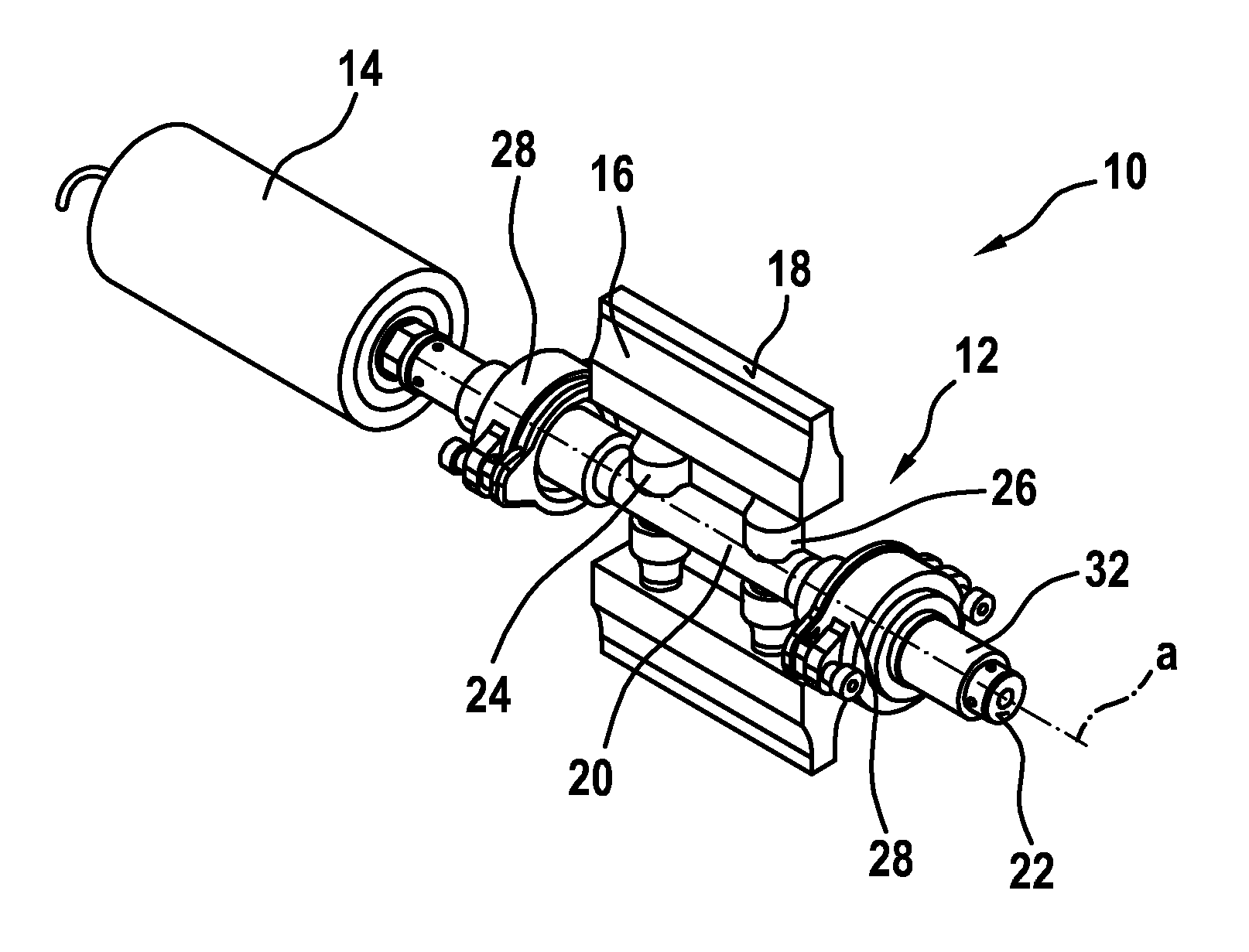
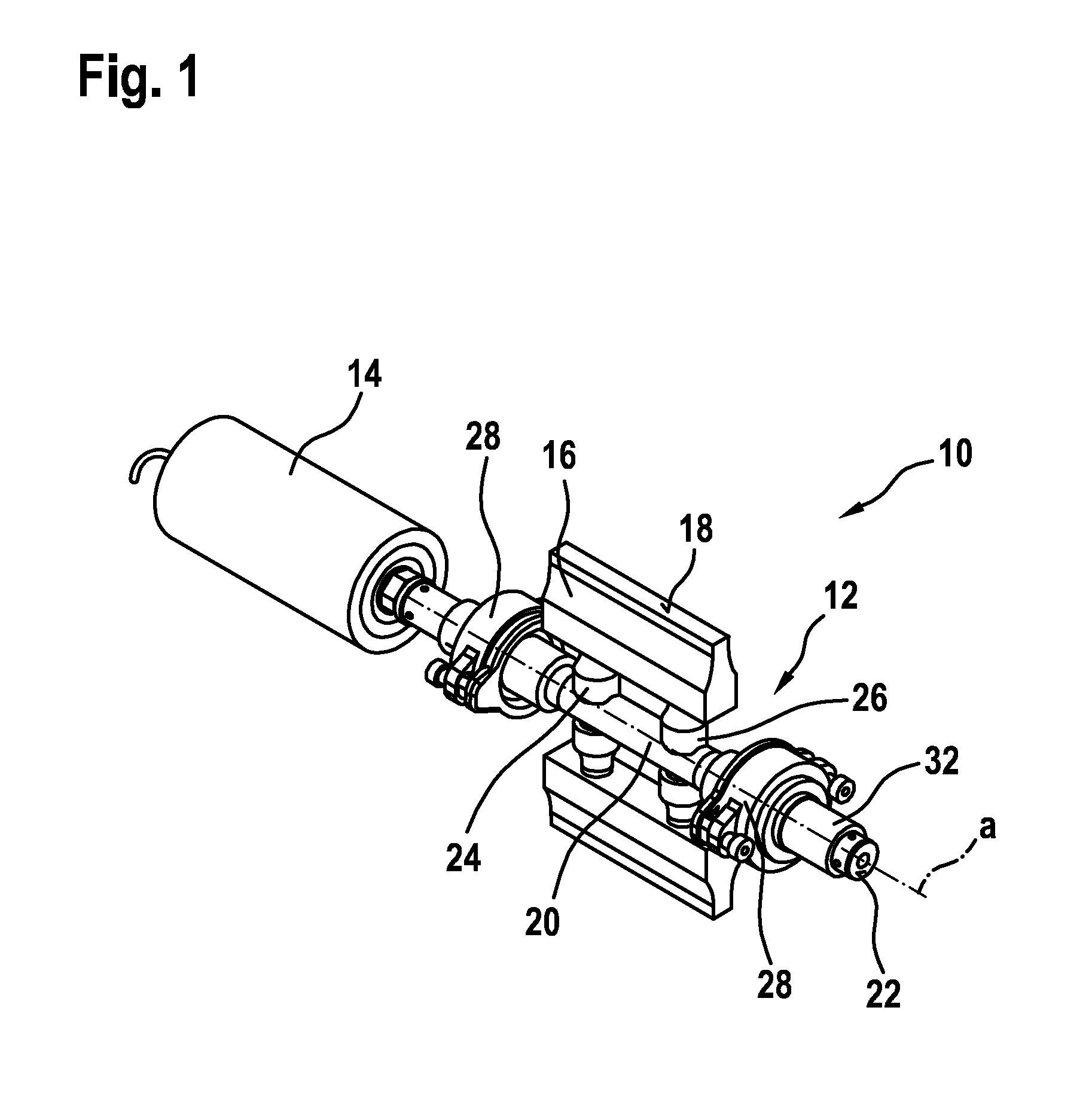
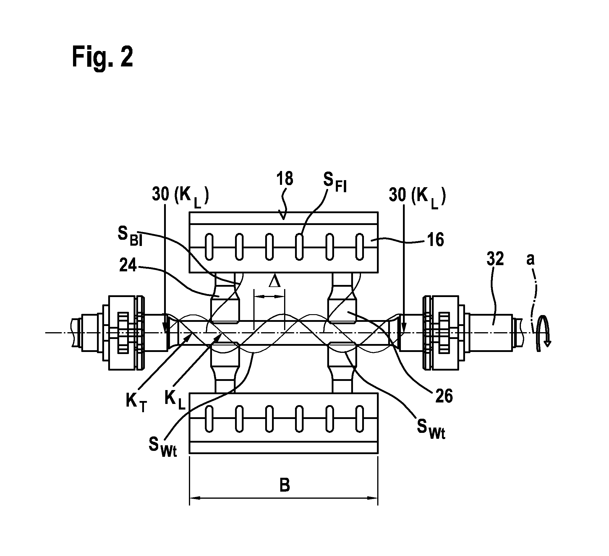
[0030]An ultrasonic vibration unit 10, which is depicted in FIGS. 1 and 2 and is for an ultrasonic welding device for producing transverse sealing seams on a tubular packaging film in a tubular bagging machine, comprises a sonotrode 12 having a sonotrode shaft, which can be rotated about an axis of rotation a and one end face 22 of which is axially connected to a converter 14. It should be noted here that both end faces 22 of the sonotrode shaft can each be connected to a converter 14, i.e. the ultrasonic energy can be simultaneously introduced from both sides into the sonotrode shaft 20. The sonotrode shaft 20 is mounted in bearings disposed on both sides thereof so that said sonotrode shaft 20 can be rotated about the axis of rotation a and is connected to a drive that is not illustrated in the drawing. Two sealing horns 16, which have a width B and comprise a terminal sealing surface 18, are attached to the sonotrode shaft 20 via in each case two boosters 24, 26. Boosters 24, 26 ...


PUM

PropertyMeasurementUnit
frequenciesaaaaaaaaaa
angleaaaaaaaaaa

Abstract

The invention relates to an ultrasonic vibration unit (10) for an ultrasonic welding device for sealing and welding material webs, comprising a sonotrode (12) connected to a converter (14) and having at least one sealing horn (16) radially protruding from an axis of rotation (a) and rotatable about the axis of rotation (a) and having a free end forming a sealing surface (18). The sonotrode (12) comprises a sonotrode shaft (20) having the axis of rotation (a). One or both end faces (22) of the sonotrode shaft (20) are connected to a converter (14) and the sealing horns (16) are attached to the sonotrode shaft (20) directly or by means of boosters (24, 26) when vibrational nodes (KL) of a longitudinal vibration (SWI) of the sonotrode shaft (20) are present.

Description

BACKGROUND OF THE INVENTION[0001]The present invention relates to an ultrasonic vibration unit for an ultrasonic welding device for sealing and welding material webs, comprising a sonotrode connected to a converter and having at least one sealing horn radially protruding from an axis of rotation and rotatable about the axis of rotation and having a free end forming a sealing surface.[0002]Ultrasonic welding is a method for joining plastics. Ultrasound is a mechanical vibration above the auditory threshold. The frequency range begins at approximately 20 kHz and extends up to frequencies of 1 GHz. Such ultrasonic frequencies are frequently produced from electrical energy with the help of piezoelectric sound transducers (converters). This mechanical vibration energy is applied to the workpiece or the material being processed via the sonotrode connected to the converter, if required via an amplitude transformation unit (booster). The surface of the sonotrode, which is provided to enter ...

Claims


Application Information

Patent Timeline
Patent Type & Authority Applications(United States)
IPC IPC(8): B29C65/08
CPCB06B3/00B29C65/085B29C66/1122B29C66/8167B29C66/83511B29C65/08B29C66/43B29C66/4312B29C66/8145B29C66/849
Inventor THAERIGEN, JAN
Owner SYNTEGON PACKAGING SYST AG
Why Eureka
Try Eureka