Simplified variable geometry turbocharger with increased flow range

a variable geometry, turbocharger technology, applied in the direction of machines/engines, stators, liquid fuel engines, etc., can solve the problems of casting wanting to “unwind”, affecting etc., to achieve simple flow control devices, increase the flow range of the turbine stage, and reduce the effect of casting stress

Inactive Publication Date: 2013-08-29
BORGWARNER INC
View PDF10 Cites 30 Cited by
  • Summary
  • Abstract
  • Description
  • Claims
  • Application Information

AI Technical Summary

Benefits of technology

[0029]The present invention relates to a simplified, low cost, variable geometry turbocharger, and more particularly, a turbine flow controlling device, which uses a divided turbine housing with assymetric volute A/Rs coupled with a flow modulation device to change the effective exhaust mass flow to the turbine wheel, while increasing the turbine stage flow range. By controlling the mass flow of exhaust, whic

Problems solved by technology

These requirements are often compromised due to other demands such as architectural requirements (space availability) outside the turbine housing, method of location and mounting of the turbine housing to the bearing housing, and the transition from slice “A” to the turbine foot (51), which combine to force turbine housing volutes to be of rectangular or triangular section, as well as in circular, or combinations of all shapes.
The reasons for this cracking are many but predominant are the dross which is pushed through the pattern at the casting process which means that the integrity of the material near the tip of the divider wall is less than optimal, and the second is the fact that the temperature distribution around the volutes causes the casting to want to “unwind”.
The thermal forces generating the “unwinding” of the turbine housing are resisted by the vertical divider wall, the resultant being cracking in the wall.
While a crack does little physical damage, the next step in cracking is for pieces of cast iron divider wall to separate from the casting and be ingested by the turbocharger or engine which can cause terminal damage.
The function of the wastegate valve, in this manner, is to cut the top off the full load boost curve, thus limiting the boost level to the engine.
This, in effect reduces the effective flow to the turbine, when desired (e.g. to prevent overdriving of the turbine), while allowing the full range of the turbine housing flow to the

Method used


Image

  • Simplified variable geometry turbocharger with increased flow range
  • Simplified variable geometry turbocharger with increased flow range
  • Simplified variable geometry turbocharger with increased flow range

Examples


first embodiment

[0075]In the invention, the effective mass flow to the turbine wheel is controlled by a flow restrictor which pivots about a point in the turbine housing inlet or foot such that in the open position the pivotable valve member (72) of the flow restrictor is in line with the divider wall (25) of the turbine housing minimizing the restriction to the exhaust flow. As more restriction, or less mass flow to the turbine wheel, is required the pivot arm (73) is actuated to rotate about its axis (74, 78) causing the pivotable valve member (72) to impede the flow of exhaust gas to the large volute (48), which causes a modulatable reduction in mass flow to the turbine wheel.

[0076]In a variation to the first embodiment of the invention, as depicted in FIGS. 11A and 11B, the flow restrictor takes the form of a butterfly valve (80) which reduces the moment on the pivot arm (81) enabling the potential use of a lower force, and thus lower cost actuator. In FIG. 11A, which is a section view of the f...

third embodiment

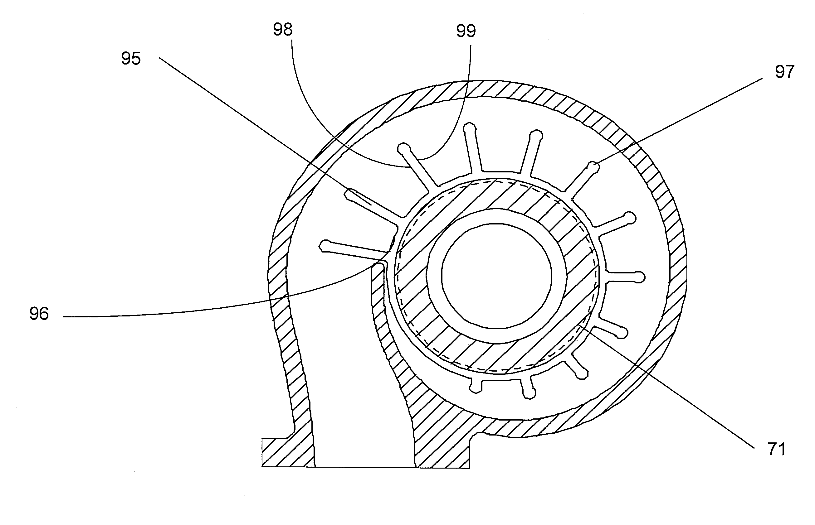
[0083]In the invention, a triple flow turbine housing as depicted in FIG. 15A is preferably used. Two axial volute divider walls (103, 104) are fabricated into the turbine housing such that the ratio of flows through the unrestricted adjacent volutes, from outer to inner are approximately 70% to 20% to 10%. These proportions can be varied depending upon requirements. The ratio of flows is only important in that the sum of the open areas of the modulated volutes is equal to the area of the modulating restrictor valve. A flow restrictor valve is provided. The flow restrictor valve pivots about a point in the turbine housing inlet or foot such that in the open position, the blade (89) of the flow restrictor is flush with the turbine housing outer volute wall minimizing the restriction to the exhaust flow. As more restriction, or less mass flow, to the turbine wheel is required, the pivot arm (73) is actuated to rotate about its axis causing the blade (89) to impede the flow of exhaust ...


PUM


Abstract

A variable geometry turbocharger is simplified yet able to maintain pulse energy. In a first embodiment, a turbine housing is provided with a pivoting flow control valve which pivots about a point near the entry to the turbine housing. By moving the valve about the pivot point, the effective volume of the turbine housing volute is varied, thus effectively reducing the volume of exhaust gas in the volute, allowing control of exhaust gas flowing to the turbine wheel. In the second embodiment of the invention, a rotating wedge segment within the volute is rotated from a first position to a second position, changing the effective volume of the volute and allowing control of exhaust gas flowing to the turbine wheel.

Description

FIELD OF THE INVENTION[0001]This invention addresses the need for a reduced cost, increased range, turbine flow control device, and accomplishes this by designing a simplified variable geometry turbocharger housing with controlled assymetric flow to the turbine wheel.BACKGROUND OF THE INVENTION[0002]Turbochargers are a type of forced induction system. They deliver air, at greater density than would be possible in the normally aspirated configuration, to the engine intake, allowing more fuel to be combusted, thus boosting the engine's horsepower without significantly increasing engine weight. A smaller turbocharged engine can replace a normally aspirated engine of a larger physical size, thus reducing the mass and aerodynamic frontal area of the vehicle.[0003]Turbochargers (FIG. 1) use the exhaust flow (100) from the engine exhaust manifold, which enters the turbine housing at the turbine inlet (51) of a turbine housing (2), to drive a turbine wheel (70), which is located in the turb...

Claims


Application Information

Patent Timeline
IPC IPC(8): F04D1/00
CPCF01D9/026F01D17/148F02B37/22Y02T50/671Y02T10/144F02B37/025F04D1/00F02C6/12Y02T10/12Y02T50/60F01D17/16F02B37/24F02B39/00
Inventor WATSON, JOHN P.GRABOWSKA, DAVID G.
Owner BORGWARNER INC
Why Eureka
Try Eureka